SPI minimal bus configuration
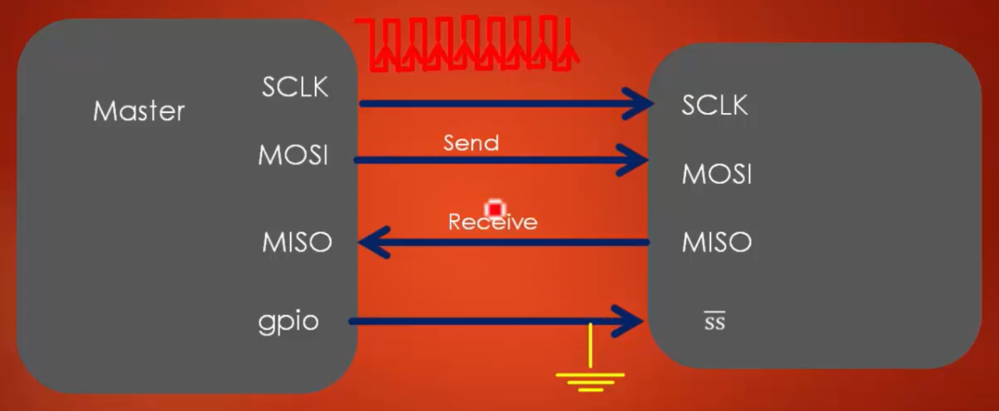
The figure illustrates a minimal SPI bus configuration, highlighting that the SPI protocol can be implemented with as few as two wires – one for clock and the other for synchronous data transfer.

This simplified configuration is suitable for certain applications where data exchange between the SPI nodes and slave select management is straightforward. In this explanation, we’ll delve into the concept of this minimal SPI bus configuration.
SPI, or Serial Peripheral Interface, is a communication protocol widely used in microcontroller-based systems for connecting a master device (often a microcontroller or similar controller) with one or more slave devices (such as sensors, memory chips, or displays). The standard SPI bus includes four essential lines: Serial Clock (SCK), Master Out Slave In (MOSI), Master In Slave Out (MISO), and Slave Select (SS or CS).
From Figure 1. The slave always receives the data, and the slave will never send any data to the master, and the master always sends the data. In this case, only two lines are sufficient for data communication between the master and slave device.
So here, all four lines are not required. Depending on the application, one can customize the SPI signals.
Important to note that in this minimal configuration:
- The master is always responsible for initiating communication and sending data to the slave.
- The slave will never send any data back to the master without additional signaling or changes to the configuration.
- The Slave Select (SS/CS) line(s), typically used to select a specific slave device, are omitted in this minimal setup. In such cases, you would need a mechanism for manually or logically selecting the slave you wish to communicate with.
In the following article, let’s see SPI behind the scene data communication principle.
FastBit Embedded Brain Academy Courses
Click here: https://fastbitlab.com/course1


