Exercise : Testing I2C interrupt APIs part 1
Now let’s test the interrupt related code and APIs using an application.
Consider the same exercise i2c_master_rx_testing (Figure 1) that we coded while testing our MasterSendData and MasterReceiveData APIs.

Steps for testing I2C interrupt APIs:
1. Create a source file: Copy the i2c_master_rx_testing file shown in Figure 1 and paste it under the src.
2. Change the name to 012i2c_master_rx_testingIT.c, as shown in Figure 2, and save it by pressing ok.

3.Exclude the 011i2c_master_rx_testing.c file from the build: Right-click on the file, go to properties (Figure 3), tick the checkbox named exclude resource from the build, and click on apply (Figure 4).


4.Change all the APIs to IT mode APIs.
5.No need to change GPIO_ButtonInit(), I2C1_GPIOInits(), I2C1_Inits(), peripheral control and I2C_ManageAcking() APIs (Figure 5). You must keep the while statement used to wait till the button is pressed, the delay function, and the statement to send the command code 0x51 (Figure 6).


6. Replace I2C_MasterSendData() API with I2C_MasterSendDataIT(), as shown in Figure 7. Remember that you have to check the return value of MasterSendDataIT() since it returns a busy state variable (Figure 8). If the busy state is BUSY_IN_TX or BUSY_IN_RX, then the application has to wait until the state becomes I2C ready.


7. Make the I2C_MasterSendDataIT() wait until the application’s state becomes I2C_READY using a while loop, as shown in Figure 9.

If the MasterSendDataIT() function returns a value not equal to I2C_READY, then the application hangs in the while loop. Otherwise, the application proceeds to the next statement.
8. Replace I2C_MasterReceiveData() API with I2C_MasterReceiveDataIT(), as shown in Figure 10.

9. Using a while loop, wait till the application’s state becomes I2C_READY (Figure 11).

10. Command code 0x52 is sent, as shown in Figure 12. Again, replace remaining I2C_MasterSendData() and I2C_MasterReceiveData() with I2C_MasterSendDataIT() and I2C_MasterReceiveDataIT(), respectively (Figure 12).

In Figure 12, the rcv_buf is a global buffer.
11. If you want to use semi hosting, then you can enable the printf statement in Figure 13.

12.You have to do the IRQ config of the I2C peripheral since you are communicating using interrupts. Now let’s do I2C IRQ configuration using I2C_IRQInterruptConfig API after peripheral configuration, as shown in Figure 14.
You have to mention the IRQ number of the interrupt as a parameter of the I2C_IRQInterruptConfig API. The I2C event interrupt and error interrupts are enabled by using IRQ numbers IRQ_NO_I2C1_EV and IRQ_NO_I2C1_ER, respectively (Figure 14).

You may also configure the priority, but that is not necessary. The priority doesn’t matter here since you have only I2C interrupts.
13. Implement the interrupt service routines for I2C1 event interrupt and I2C1 error interrupt:
- Go to the startup code(startup_stm32.s) to get the ISR name.
- Search for I2C1, as shown in Figure 15.

- Copy the ISR names, shown in Figure 16.

- Go to the application and create the IRQ handlers at the end, as shown in Figure 17.

- Inside IRQ handlers of Figure 17, you have to call the IRQ handling APIs, which are already developed. Now call I2C_EV_IRQHandling, as shown in Figure 18, and pass the address of the handler (I2C1Handle) as a parameter.

Whenever an event happens during the I2C communication, the I2C1 event handler will be called, where the event IRQ handling APIs are called in order to decode that event and take the appropriate action. Whereas in the case of error, IRQ handling APIs are called.
- Once the control enters into the IRQHandling API, the IRQHandling API notifies the application about the different events through the callbacks. Therefore now you have to implement I2C_ApplicationEventCallback() in your application.
a. Create the function I2C_ApplicationEventCallback() (Figure 19).

b. Figure 20 shows the various events generated by the driver and are defined in the driver header file. You can check for all these events.

c. For example, in our application, let’s check for TX complete, RX complete, and errors in the semi hosting, as shown in Figure 21.

Here I2C_ERROR_AF means ACK failure. Now the question is, why the ACK failure happens? For example, in master, the ACK failure happens when a slave fails to send ACK for the byte sent from the master. That means the master has sent 1 byte but didn’t receive the ACK from the slave, resulting in ACK failure.
d. When ACK failure occurs in the case of a master, then you can conclude something like slave device might have been removed from the bus or slave device might have gone bad or it may not want more data. Therefore, the master should close the communication by calling I2C_CloseSendData() API, as shown in Figure 22, and should not send more data to the slave.

e. In the definition of I2C_CloseSendData() API (Figure 23), we turn off a couple of interrupts, and we make TxRx state as I2C_READY, TxBuffer=NULL, and TxLen=0.

f. The stop condition is didn’t generated in the CloseSendData() API. Therefore, you have to generate the stop condition in the callback function to release the bus. There is an API to generate the stop condition, which is a private API. But if the application wants to release the bus, then the application should call generate stop condition API. Therefore, now you have to make this API as public instead of private. For that, first cut the API shown in Figure 24, then go to the driver file and paste the API under the peripheral control APIs section and remove the static keyword (Figure 25).
Also, remove the static keyword from the definition of GenerateStopCondition() API.


Since the GenerateStopCondition() API is made public, now you can call it from the application callback function, as shown in Figure 26.

g. Look at Figure 27. If ACK failure occurs in the very first line, then the application should not go further. Because the ACK failure happened in the first line itself and for our application, executing the second line without executing the first line doesn’t make any sense. Therefore, the program control must hang in the application callback function (Figure 27) to pause code execution.

14. Since you have used a printf statement, it is necessary to enable the semi hosting (Figure 28 and 29).


15. On the Arduino side, download the sketch 002 I2CSlaveTxString (Figure 30).

16. Compile the code (Figure 31).

17. There seems to be one warning, as shown in Figure 32.

18. To solve this problem, you have to extern the initialise_monitor_handles() shown in Figure 33 by enabling the statement in Figure 34.


19. Again, build the project. Now the project builds successfully without any errors (Figure 35).

20. Download the code into the chip.
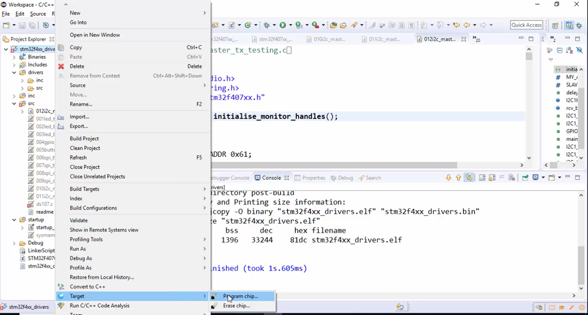
21. Go into the debug mode (Figure 37). You can see debug mode in Figure 38, and it is saying that semi hosting is enabled.
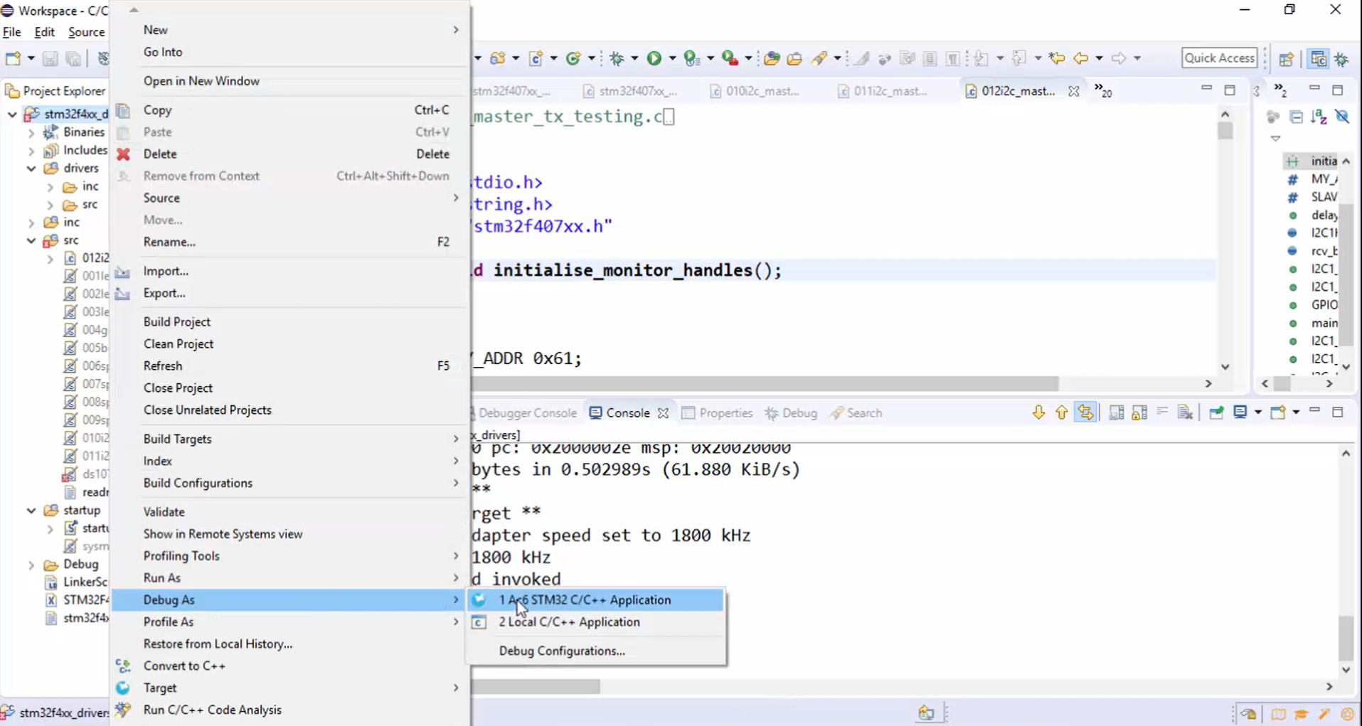

22. Go to the breakpoints and remove all (Figure 39).

23. Hit the resume button (Figure 40). Now the code is running, and you have to press the user button.

24. Start tracing by pressing the user button (Figure 41).

You can see the I2C trace of your application in Figure 42.

25. Observe the console in Figure 43. Application is running, Tx is completed, Rx is completed, Tx is completed, but the data is not received.

Look at the trace in Figure 44, the data is received, and the last 4 characters of data are EBA and \n. But the data is not printed on the console. The problem is the program has to wait until the receive completes. Without that, you cannot proceed to the next line, or you cannot execute the printf statement in Figure 45.


26. To solve this problem, set the rxComplt flag after Rx completed, as shown in Figure 46.

27. Declare the flag variable (Figure 47).

28. In the application after the while statement, wait until the rxComplt variable is set, as shown in Figure 48. After printing the data, you can make rxComplt = RESET again.

29.Remember that you have one more MasterReceiveData() API. After the completion of receive data here also the ApplicationEventCallback() will be executed for the event I2C Rx complete, and the flag will be set. Therefore, before checking whether rxComplt is set or reset, make sure that you clear the rxComplt flag, which was set for the previous MasterReceiveData event. That means RESET the rxComplt variable, as shown in Figure 49.

30. Build the project. There is one warning saying while clause does not guard. Basically, this warning is harmless; you can keep it as it is. But if you want to solve this warning, remove the semicolon of while and give the guards, as shown in Figure 50.

31. Build the project. Now the project is error-free.
32.Program the chip (Figure 51).

33. Go to the debugging mode (Figure 52).

34. Now you are in the debugging mode (Figure 53). Reset the Arduino board and remove all the breakpoints.

35. Hit the run button (Figure 54).

36. Hit the user button. Now you can observe that the data is received from the slave (Figure 55).


