LCD module interfacing explanation on various boards
In this article, we will explore the workings of STM32CubeIDE and the connection between the microcontroller and display. Specifically, we will focus on the interfacing of the LCD module with the STM32F429IDISCOVERY Discovery kit.
Let’s begin by understanding how the LCD module is connected to the microcontroller.
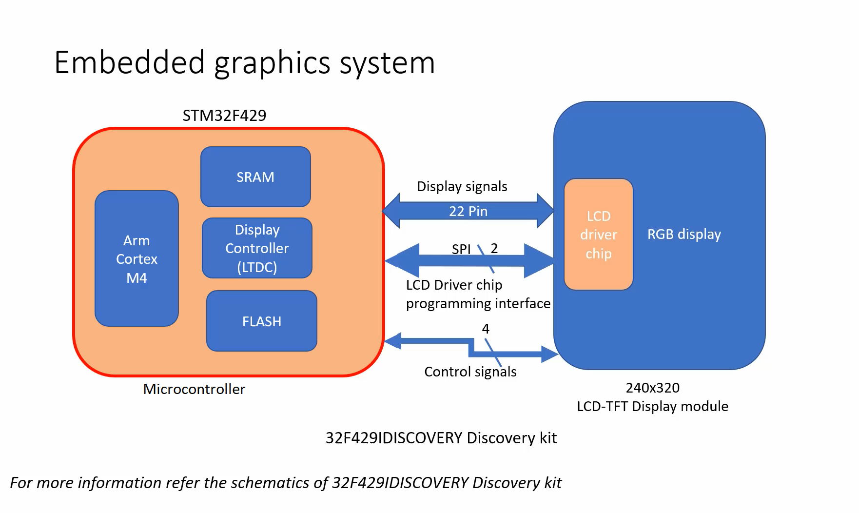
In Figure 1, you can see a microcontroller and an LCD-TFT display module in the 32F429IDISCOVERY discovery kit.
The module uses three types of interfacing signals:
- Display signals
- SPI communication
- Control signals
Display signals
The display signals are transmitted through 22 pins, which the microcontroller uses to send color information. It’s important to note that the internal connection handles everything automatically, so you don’t need to take any extra steps.
All essential connections are pre-established, given that the display module is already integrated into the development board. While no extra connections are necessary, we will elucidate the involved signals for your comprehension.
SPI Communication
In addition to the existing connections, there is another interface between the microcontroller and the display module called SPI communication. The SPI interface is used for LCD driver chip programming. I mean, before you send any display signals over this interface, you should keep the LCD driver chip in a certain mode, so that it can properly interpret these display signals coming from the HOST.
After resetting the board, the LCD driver chip may not be in the proper mode to interpret the signals coming over the display lines. You should first program this LCD driver chip using the SPI interface by sending some commands, and that is already happening in the project which we just tested.
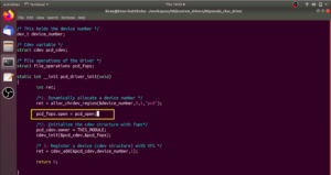
I can show you where it’s happening. I go to the project and open the main.c file, and you can see in the main function that we perform LCD initialization before sending anything, as depicted in Figure 2.
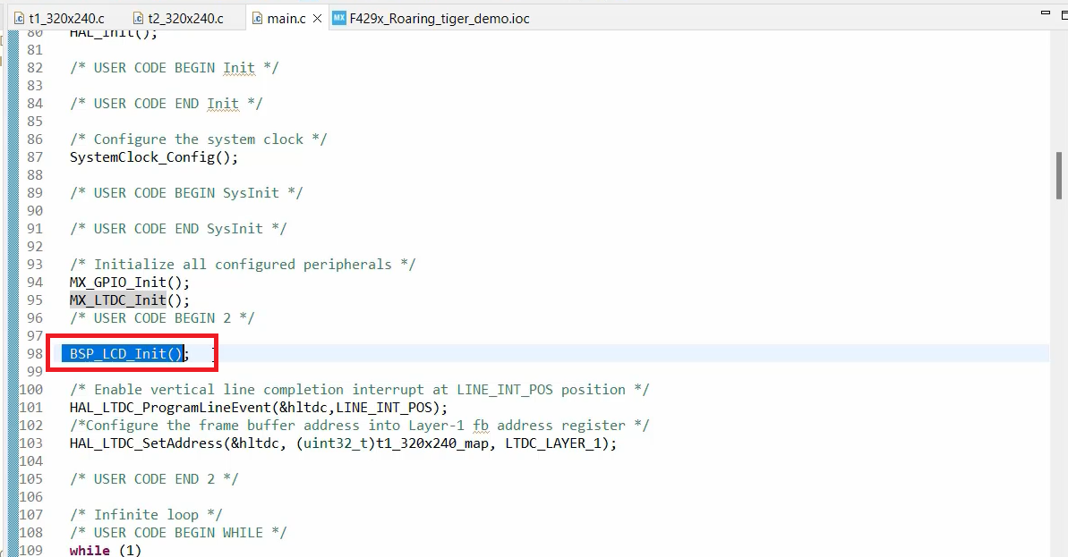
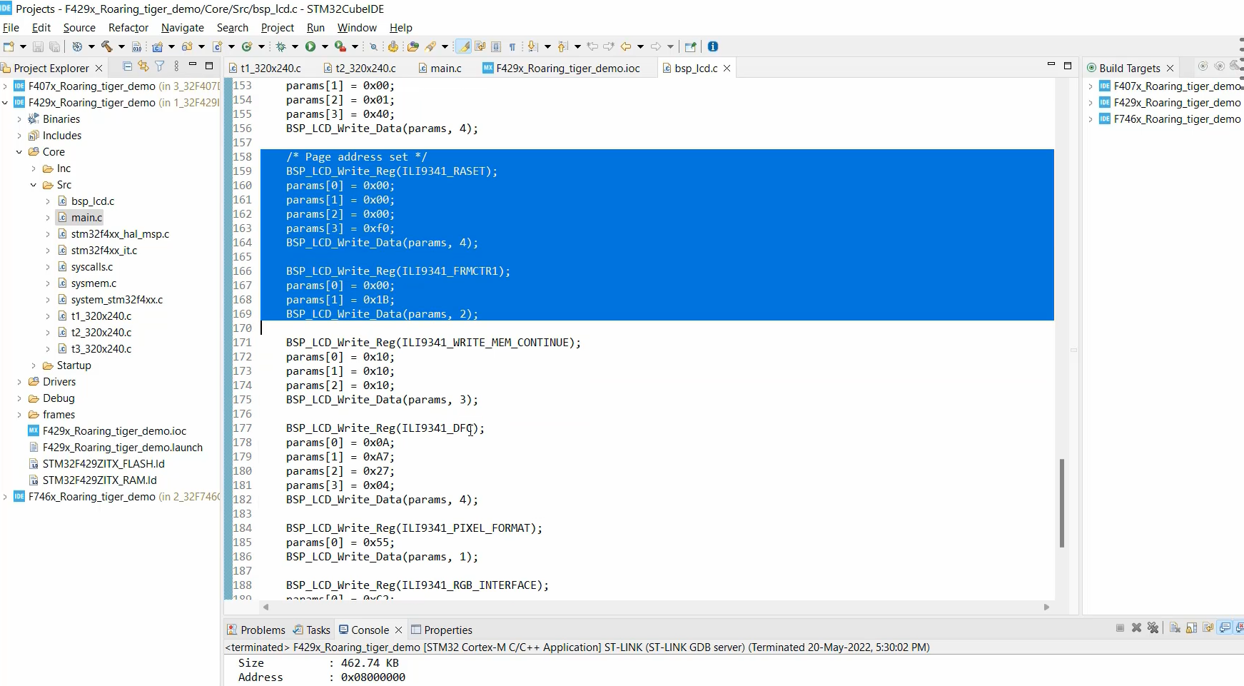
Going under the LCD initialization function, we can see that this function is sending various LCD driver chip related commands to initialize it and to keep that in a proper state.
There are also a couple of control signals involved for the LCD driver chip and these control signals have to be controlled by the Host(Figure 1). Otherwise, the driver chip may not interpret what is data, what is a command, etc. This is just a bird’s view of how things are working.
In the case of the STM32F746GDISCOVERY Discovery kit, the interface is pretty much simple.
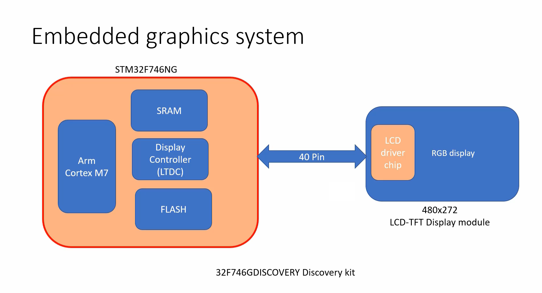
There is just one 40-pin connector, which goes from the baseboard to the display module. Here, there is no LCD driver chip programming interface, because this LCD driver chip is pretty much simple and it doesn’t have any modes.
So, when you just reset it, it can directly interpret the display signals coming out of these lines(40-pin connector). You need not keep that driver chip in any mode. And you know it’s just a 40-pin connector.
To understand the precise pin details, you should always consult the schematics of the development boards.
What is the display module?
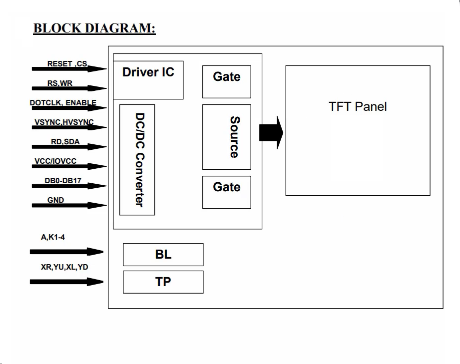
As per the MIPI standard, the meaning of display module is a functional module to show image on it, can consist of display glass (that is the TFT panel), display driver IC, other peripheral components and circuits, and a display interface.
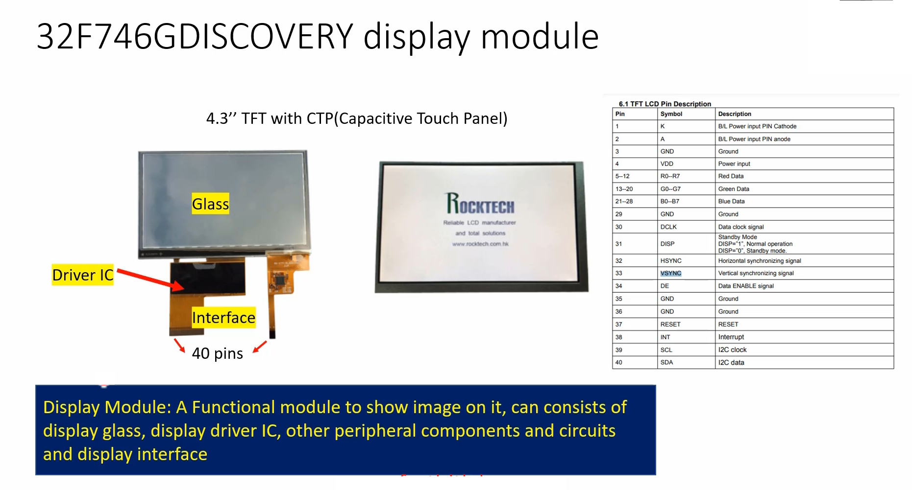
That’s why collectively it is called the Display module. Look at Figure 6, RESET, CS, RS, ER, these are the signals coming from the host.
Get the Full Course on STM32-LTDC, LCD-TFT, LVGL (MCU3) Here.
FastBit Embedded Brain Academy Courses
Click here: https://fastbitlab.com/course1