Analyzing RGB interface signals
In this article, let’s understand more about DPI control signals. Look at Figure 1, I have captured the Control Signals trace.
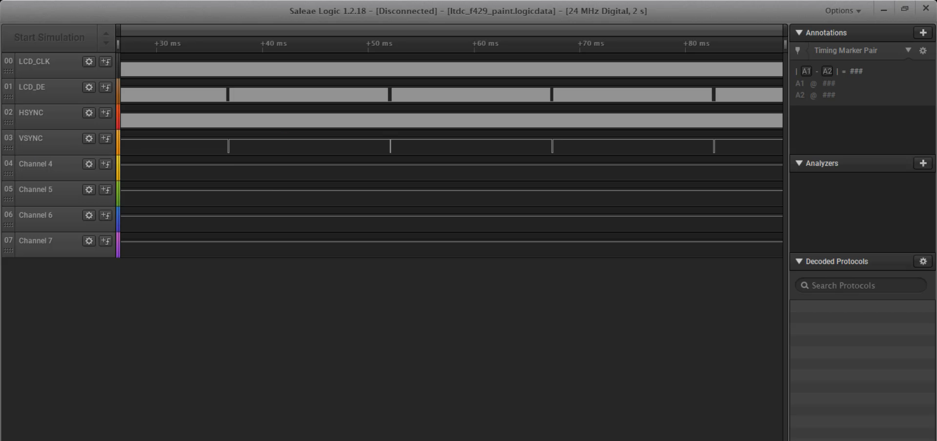
The DOTCLK signal (also known as LCD_CLK or PCLK), Data Enable, HSYNC, and VSYNC signals can be found on the STM32429 board, and you can refer to the schematic of the board to locate the specific pin to probe. Unfortunately, these signals cannot be accessed on the F7 board as it doesn’t provide expansion header pins.
You can go through the trace to understand more about how these signals interact, and this will be helpful while debugging your code.
If something is not working, then you can always probe the signals and understand what’s going on. And I have not probed the data lines here, which is not required.
Let’s start with Vsync.
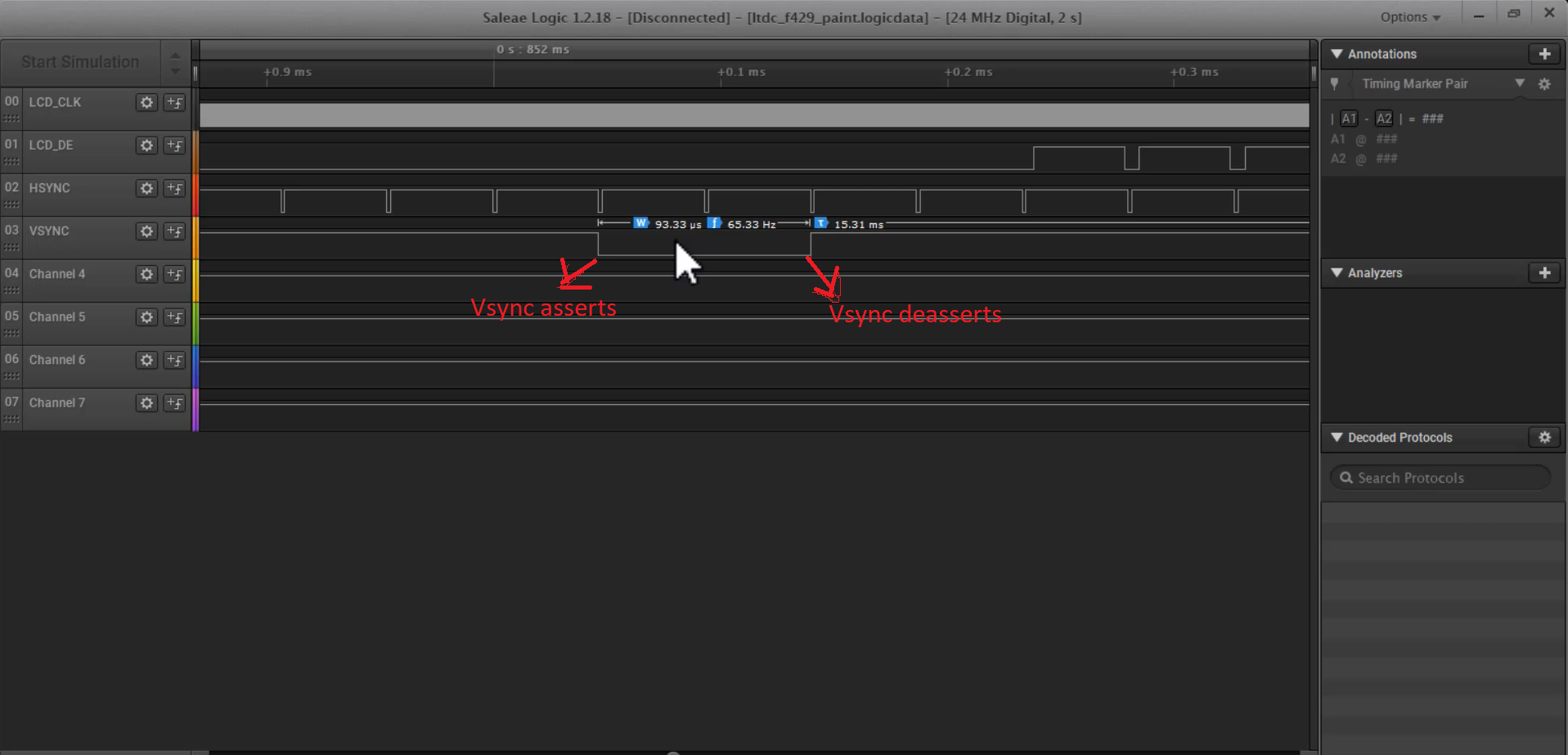
Look at Figure 2, you can see here the Vsync assertion(it is active low) and Vsync de-assertion. Here is the width of the Vsync, which is 93 microseconds. So, you have to check the datasheet of the LCD modules driver chip to understand what exactly the width should be. These are all configurable parameters.
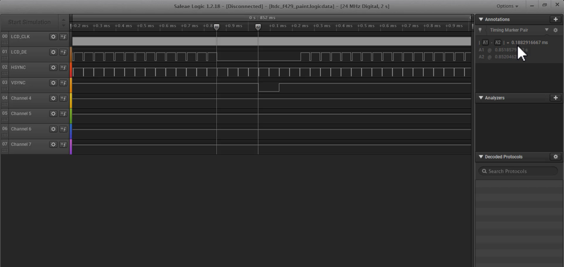
And here you can also observe that, before the vsync assertion, the DE signal is already deasserted, as shown in Figure 3. The LCD_DE went low here. Whenever DE = 0, that means the data lines are not valid. So, the LCD module will not latch the data lines in this duration, because DE = 0 here.
By the way, this is a pixel clock, which is 6 megahertz.
And you can also see that once DE deasserts here, and after 4 Hsync duration Vsync asserts here. This duration from A1 to A2 is around 0.18 milliseconds. This is called the Vsync’s front porch(VFP).
First what happens is, DE goes low and the LCD module understands that the data are not valid, that’s why, it will not latch the data here.
After that, after 4 Hsync duration, the Vsync asserts. This duration is called A1 to A2 vertical front porch of the Vsync.
After that, Vsync deasserts, as shown in Figure 4.
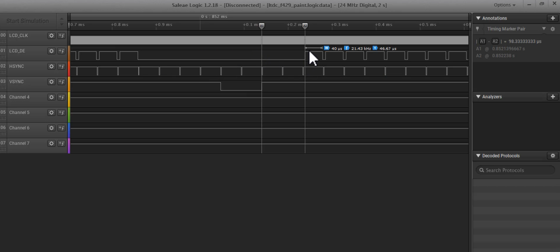
Once the Vsync deasserts, the DE will not go high immediately. So, it takes two Hsync duration. And this duration A1 to A2 is around 96 microseconds. It is called the vertical back porch of the Vsync(vbp).
Let’s check Hsync, as shown in Figure 5.
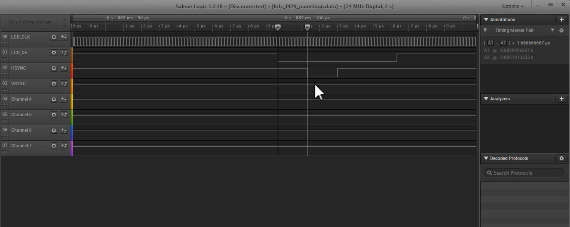
You can see that before Hsync asserts here, DE has already gone low here. So, you can say that from A1 to A2 here, this is the front porch of the Hsync(Hfp), which is around 1.6 microseconds.
Here is the width of the Hsync, which is around 1.6 microseconds.
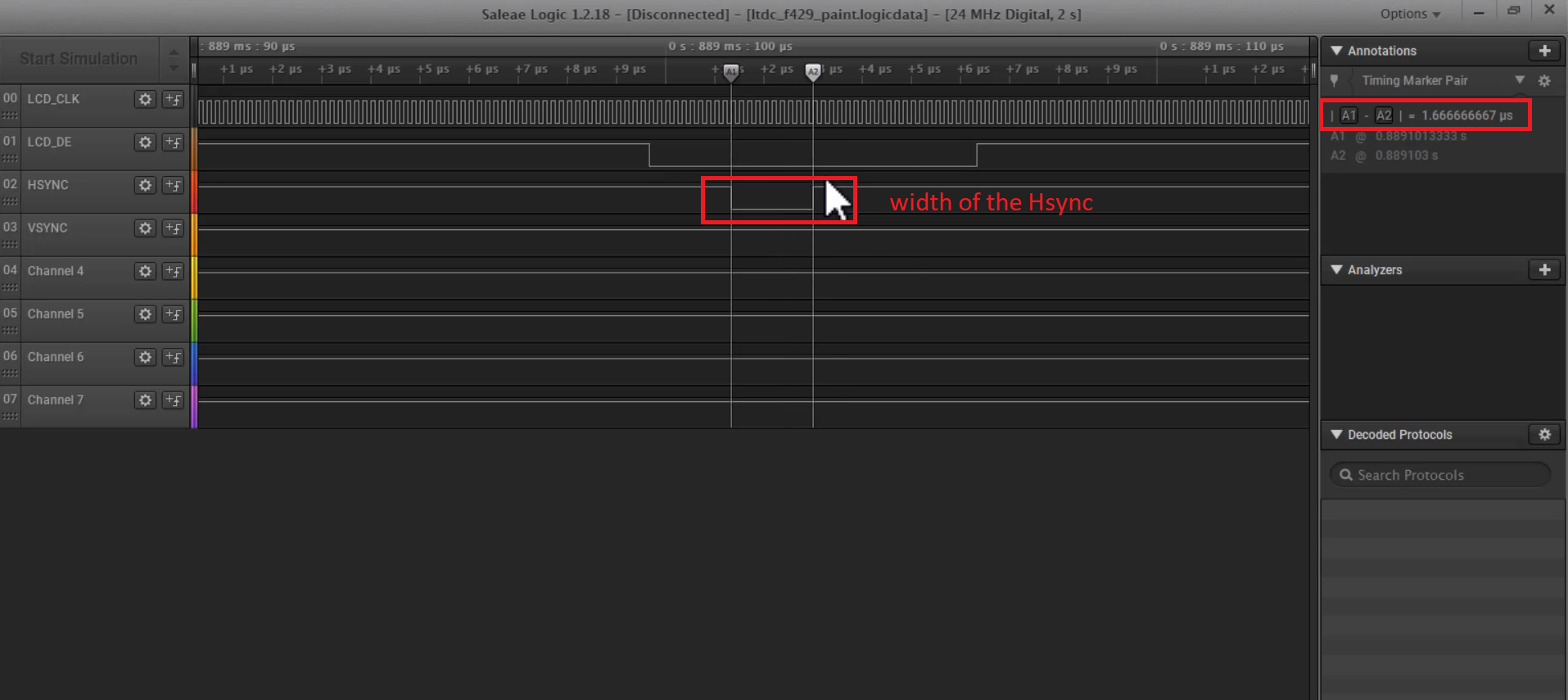
And once Hsync deasserts here, DE will not go high immediately, but it takes some time. You can see that, which is called an Hsync back porch(HBP).
All these parameters like Hsync width, HBP, HFP, Vsync width, VFP, and VBP, are all configurable parameters and you have to check the datasheet of the display module to understand the numbers, and you have to program that in the LTDC controllers registers. So, the LTDC can produce the timing signals according to that. It is specific to the display module.
As you can see in Figure 7, this is the width or duration of one line. It is around 40 microseconds. Duration to send one line.
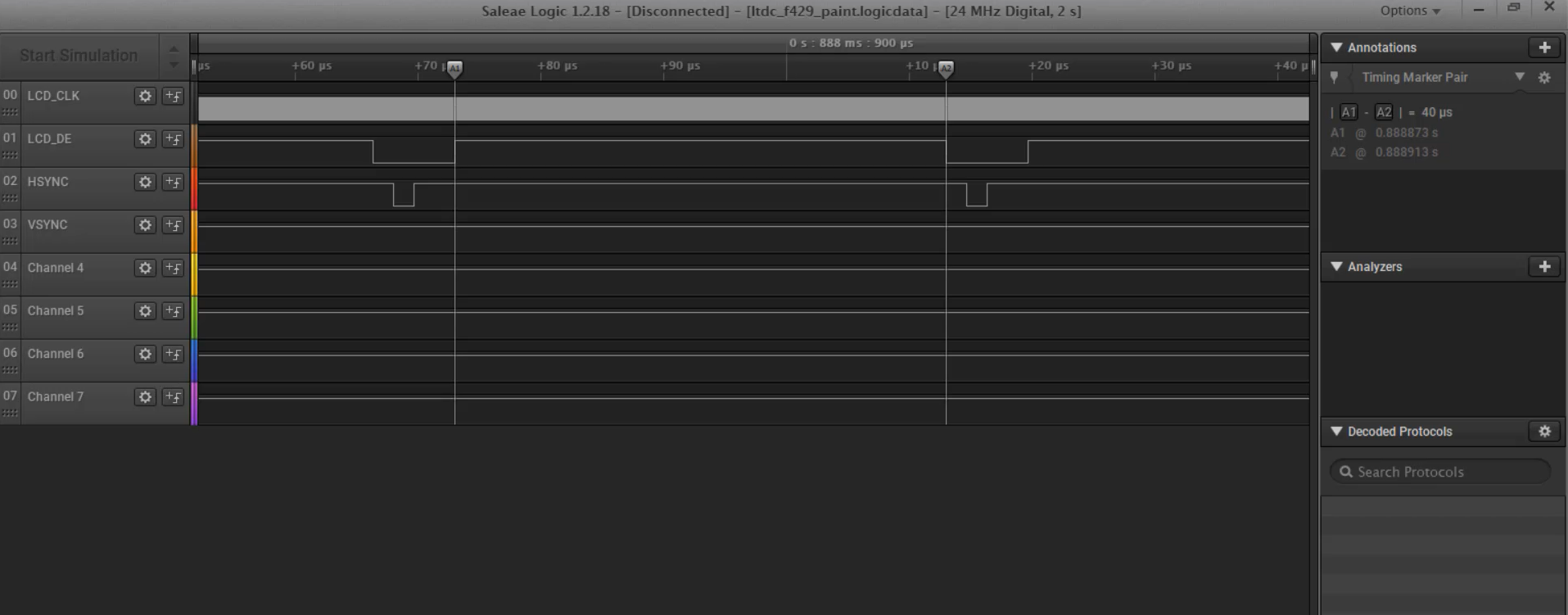
What is 1 line?
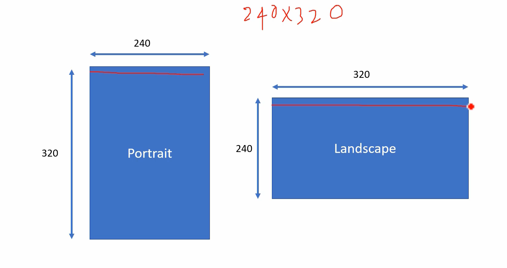
That depends on display orientation. Let’s consider the display of 240×320 resolution. If you are using portrait orientation, then 1 line means 240 pixels. But, if you are using landscape orientation, 1 line means 320 pixels.
Look at the datasheet of the ILI9341 LCD driver Chip. Here they have mentioned what values to configure for HBP, HFP, VBP, and VFP, and also for Hsync width, and Vsync width.
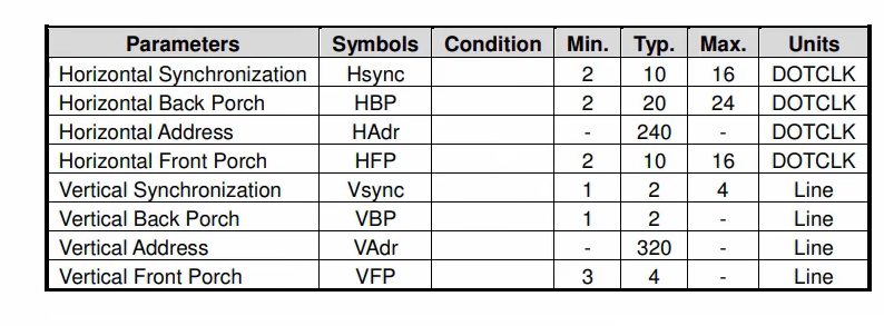
First, let’s see the horizontal synchronization(Hsync) numbers. So, the Hsync, HBP, and HFP, all these are measured in DOTCLK.
For example, here Hsync width is typically a 10-pixel clock(DOTCLK) period. That’s the meaning of this.
HBP is 20 pixel clock period or DOTCLK period.
Please note that DOTCLK is 6 megahertz in our case. But Vsync parameters are measured in lines. For example, Vsync width is typically two lines or two in duration.
In the trace(Figure 2), Vsync width, you can see that two line duration. And the front porch is 4-line duration. That’s why, the vertical synchronization parameters are measured in a number of line duration.
And please note that these numbers are different for different chips.
You really have to check the datasheet. And these numbers, horizontal address or vertical address depend on the orientation as I said. If it is 240 here, that means you are driving the LCD module in portrait orientation. If it is 320, then you are driving it in landscape orientation.
So, the trace will really help you if something is not working. You must see all these signals coming out of the LTDC controller to drive the RGB interface-based LCD module.
If any of these signals are not coming or if some duration is not matching with your calculations, then you will get some hints to troubleshoot your problem.
Get the Full Course on STM32-LTDC, LCD-TFT, LVGL (MCU3) Here.
FastBit Embedded Brain Academy Courses
Click here: https://fastbitlab.com/course1