Setting up main system clock code implementation part-5
Turn on PLL and wait for PLLCK ready
Here, I used the REG_SET_BIT macro. Because I have to set only one bit, so I would use this macro.
After that, I just wait until the PLLRDY bit is set. So, I use the while loop to hang here until that bit is set.
//Turn on PLL and wait for PLLCLK ready
REG_SET_BIT(pRCC->CR,RCC_CR_PLLON_Pos);
while(!REG_READ_BIT(pRCC->CR,RCC_CR_PLLRDY_Pos));
Switch PLLCLK as SYSCLK
//Switch PLLCLK as SYSCLK
REG_SET_VAL(pRCC->CFGR,0x2U,0x3U,RCC_CFGR_SW_Pos);
while(!(REG_READ_VAL(pRCC->CFGR,0x3U,RCC_CFGR_SWS_Pos) == 0x2U));
In this step, I switch PLLCLK to SYSCLK. And by using REG_READ_VAL, I just make sure that the status is 2. If the status is 2, then it means PLLCLK is now acting as the system clock. So, you have to wait until that status is updated by the hardware.
However, it is important to note that programming the flash wait states after this step is not the correct method. Before boosting the HCLK to higher frequencies, the flash wait states must be configured properly. Therefore, it is necessary to configure the flash wait states before proceeding with the HCLK configuration.
Program flash wait states
Here you can see that I program the value 5.
void SystemClock_Setup(void)
{
RCC_TypeDef *pRCC = RCC;
FLASH_TypeDef *pFlash = FLASH;
PWR_TypeDef *pPWR = PWR;

//Program flash wait states
REG_SET_VAL(pFlash->ACR,0x5U,0xFU,FLASH_ACR_LATENCY_Pos);
Over drive Settings
//Over drive settings
REG_SET_BIT(pRCC->APB1ENR,RCC_APB1ENR_PWREN_Pos); /*Enable clock for PWR register access*/
REG_SET_VAL(pPWR->CR,0x3,0x3,PWR_CR_VOS_Pos); /*VOS = 0b11*/
REG_SET_BIT(pPWR->CR,PWR_CR_ODEN_Pos); /* Activate over drive mode */
while(! REG_READ_BIT(pPWR->CSR,PWR_CSR_ODRDY_Pos)); /* wait for overdrive ready*/
REG_SET_BIT(pPWR->CR,PWR_CR_ODSWEN_Pos); /* Over drive switch enable*/
Afterwards, you will need to make one more setting, which is the Overdrive setting.
Let me explain what that entails. If you simply open your device datasheet (not the reference manual), you will find the table below, as shown in Figure 1.
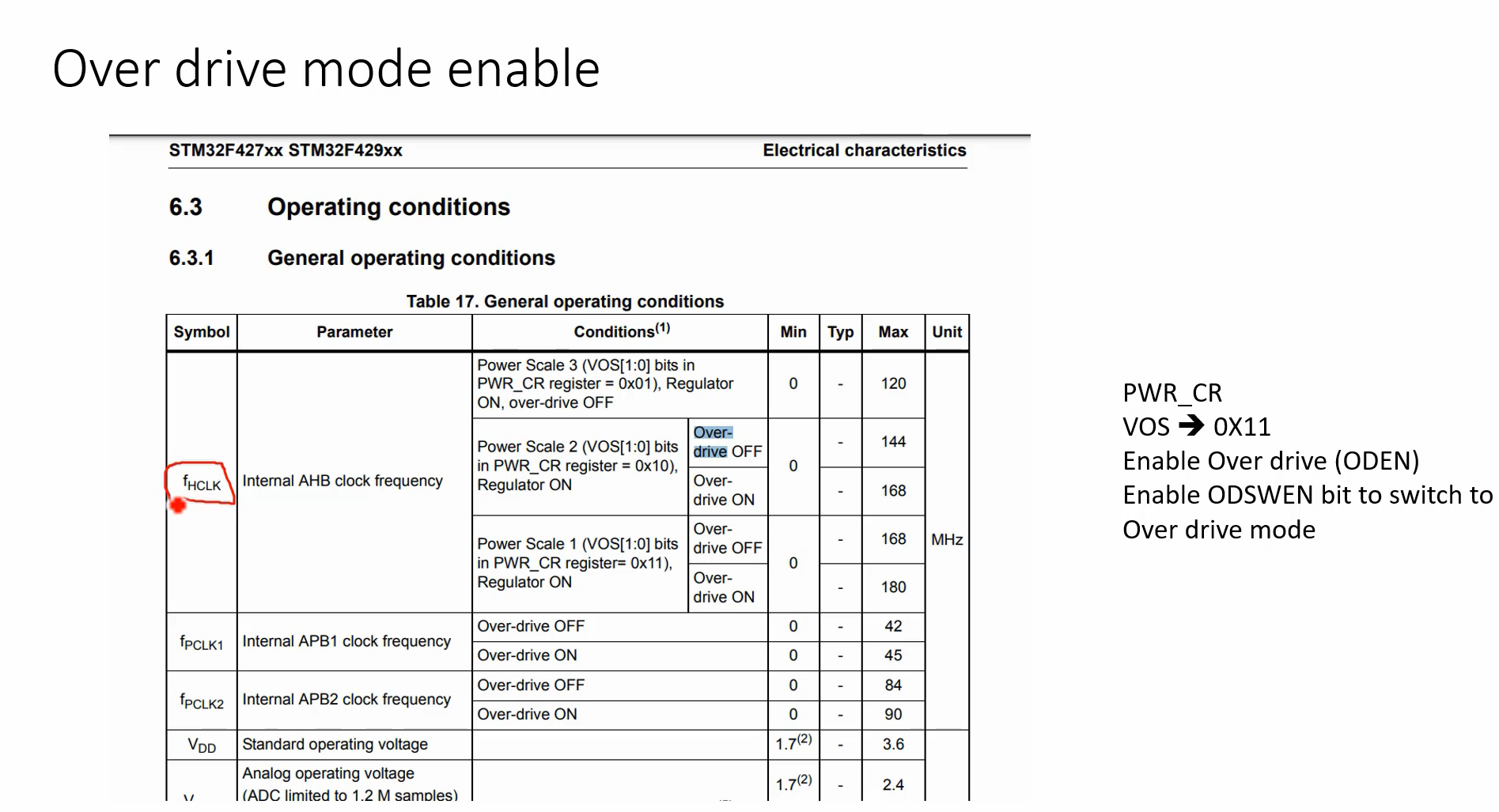
There are different power scaling modes available to achieve higher HCLK, and this is done to save power.
For example, Power Scale 1 mode consumes more power compared to Power Scale 2 and Power Scale 3. By default, after reset, the microcontroller will be in Power Scale 1.
When the microcontroller is in power scale 1 mode, it can be driven to achieve HCLK of either 168MHz or 180MHz. However, in order to achieve 180MHz, the Over-drive mode must be turned on. By default, the Over-drive mode is off and the maximum achievable frequency is only 168MHz. So, to boost the clock further, you have to now turn on the Over-drive mode.
For that, enable the Overdrive bit in the power register, and then switch to Overdrive mode. This is demonstrated in the Overdrive setting in Figure 2.
To access the power register of the microcontroller, you need to access them through the APB1 domain. Therefore, you must first turn on the clock for the power registers using the APB1ENR register of the RCC APB1 clock enable (line 50).
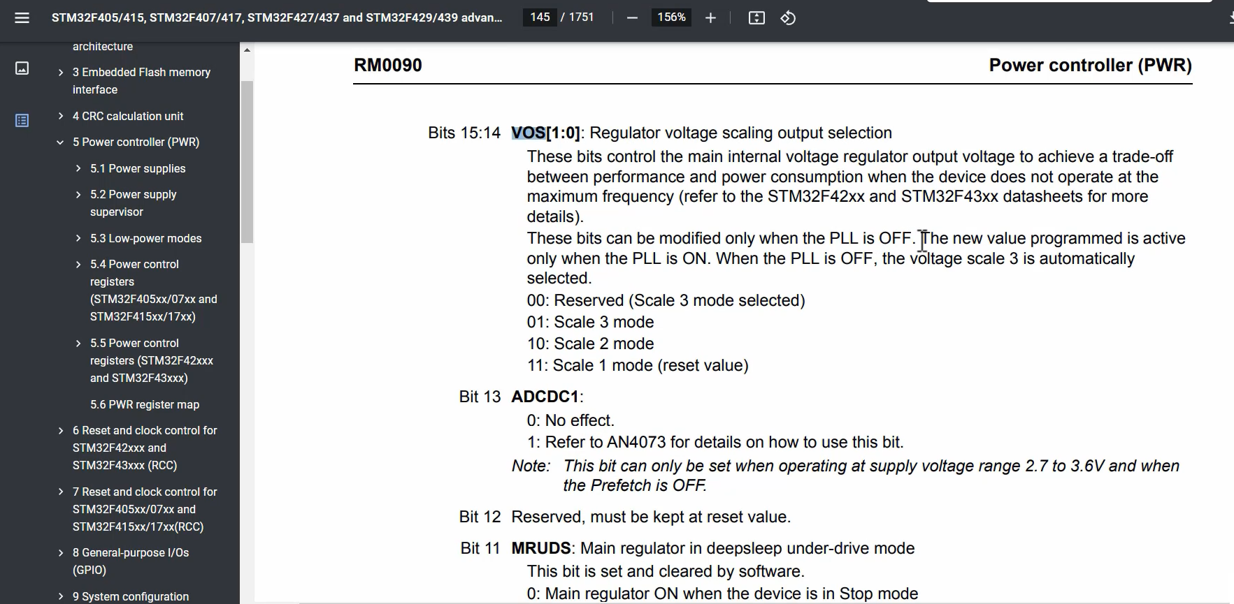
After that(line 51), this sets a VOS field to value 3.
To better understand VOS, refer to Figure 2.
VOS : Regulator voltage scaling output section
You can see here, these bits can only be modified when PLL is OFF. That’s why the program it to scale 1 mode.
After that, in the PWR_CR register, you must first enable the Overdrive mode. To access the ODEN bit, either the HSI or HSE must be selected as the system clock.
So, obviously, you cannot do this after you switch PLL as a system clock. Once you have made this selection, the application must wait for the Over-drive ready flag to be set.
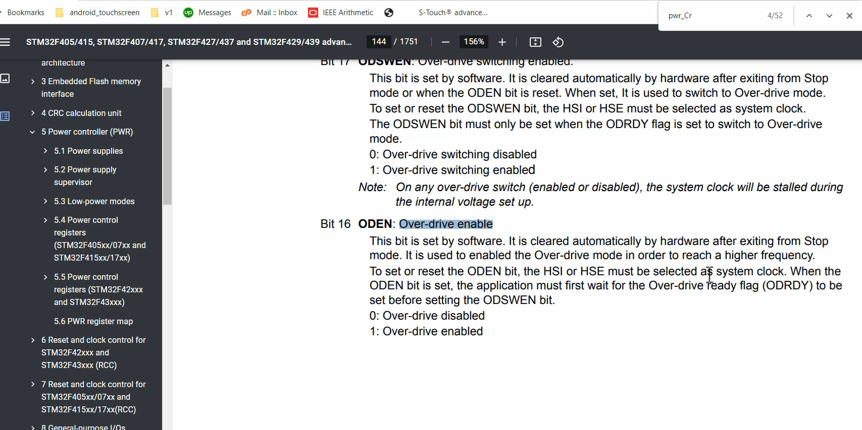
I activate Overdrive mode , and then wait for Overdrive to be ready. After that, you need to handle the ODSWEN (Overdrive Switching Enabled) bit..
If you complete all these steps successfully, then you must see the system clock as 180MHz. If that is 180MHz, and if you have configured the prescalers properly, the HCLK will also be 180MHz for this microcontroller.
In the following article, we will measure the system clock to see whether it is really 180MHz or not. If it is 180MHz, then our settings are correct. And if it is not 180MHz, then there must be some mistakes in our code. So, we’ll see whether the SYSCLK is 180MHz or not.
FastBit Embedded Brain Academy Courses
Click here: https://fastbitlab.com/course1