LCD SPI initialization coding part-1
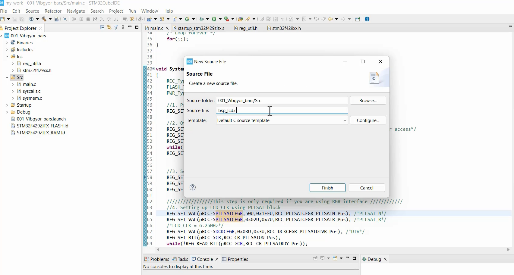
In the ‘Src’ folder, we need to create a new source file called bsp_lcd.c, where we will keep all the code related to the LCD.
Basically, it’s one of the peripherals mounted on our board. That’s why I use the word BSP(board support package or board support code).
This board support gives us one function called BSP_LCD_Init.
This function should initialize all the necessary pins, programming interfaces, and LTDC interface (if required), and send various commands to the LCD to set its mode and preferences. All these steps will be coded step by step.
First, let’s define all the LCD signals using the macros.
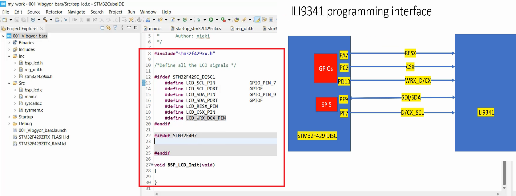
Look at Figure 1, here is a piece of C code that includes the header file “stm32f429xx.h” which defines the register addresses and bit fields for the STM32F429 microcontroller.
/*Define all the LCD signals */
#ifdef STM32F429I_DISC1
       #define LCD_SCL_PIN        GPIO_PIN_7
       #define LCD_SCL_PORT       GPIOF
       #define LCD_SDA_PIN        GPIO_PIN_9
       #define LCD_SDA_PORT       GPIOF
       #define LCD_RESX_PIN
       #define LCD_CSX_PIN
       #define LCD_WRX_DCX_PIN
#endif
The code also has an “ifdef” preprocessor directive, which checks if the macro “STM32F429I_DISC1” is defined.
The RESX pin of this ILI9341 controller is connected to PA7. That’s why I write GPIO_PIN_7.
So, SCL is GPIO_PIN_7 of port F, that’s why, I created one more macro #define LCD_SCL_PORT and initialize this to GPIOF. So, GPIOF is the base address of the GPIOF peripheral. It is there in the stm32f429xx.h header file. That’s why I include the header file here.
Likewise LCD_SDA_PIN. SDA is PF9. So I write GPIO_PIN_9, and let’s create one more macro here called PORT.
#define LCD_SDA_PORT GPIOF
Like this complete for the rest of the pins.
To support both the STM32F429 and STM32F407 boards, I created a single macro (line 12 and line 22). Additionally, you can create another block here for STM32F407, and create similar macros by referring to the ILI9341 interfacing diagram and initializing them with the appropriate PINs and port names.
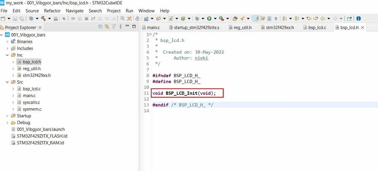
Next, let’s add the bsp_lcd.h file to the Inc folder, and here include the BSP_LCD_Init function as a prototype:
void BSP_LCD_Init(void);
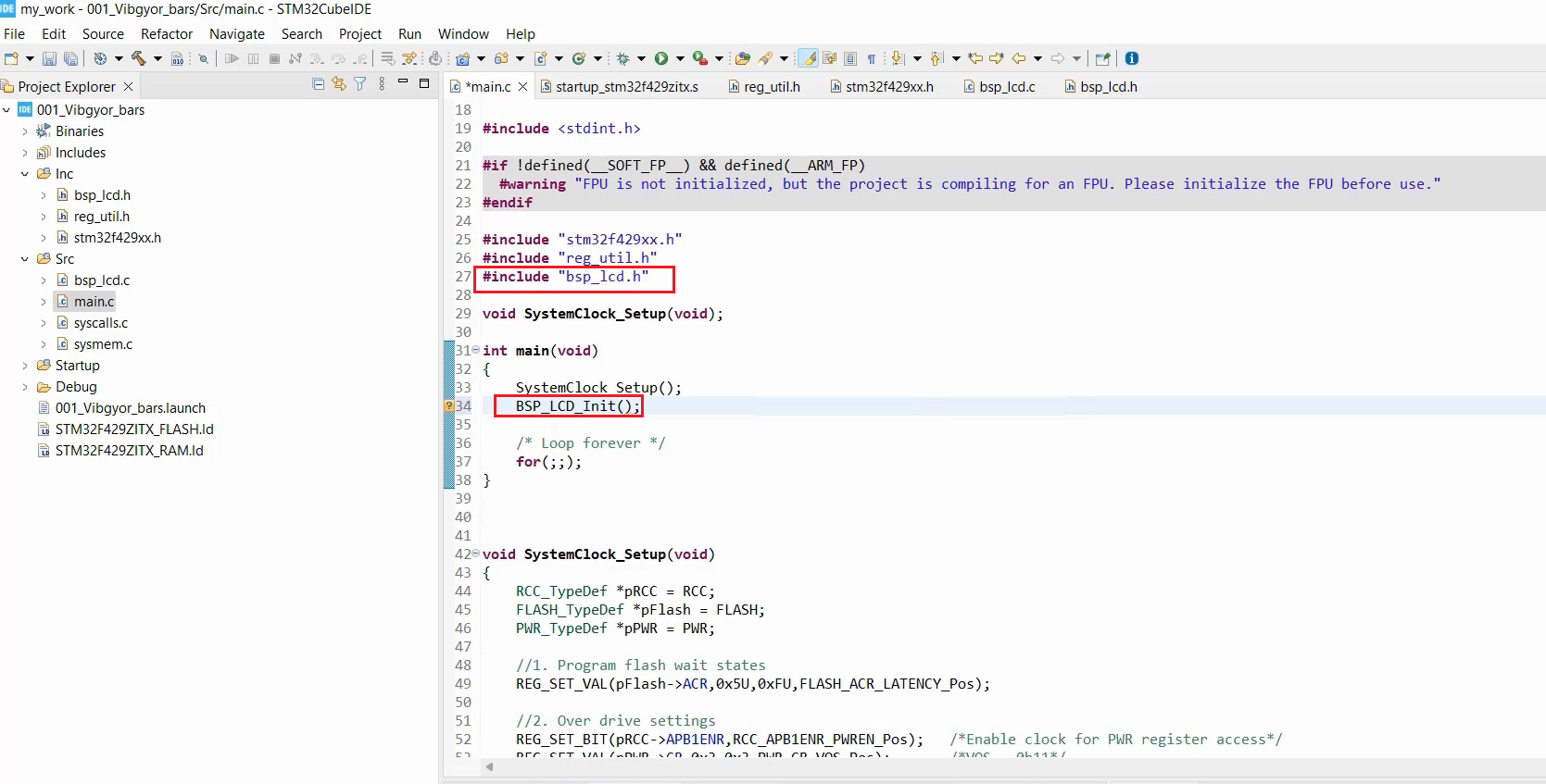
In the main.c, you have to include that BSP file. If it wants to use the LCD, maybe it calls that BSP_LCD_Init from here, as shown in Figure 4.
FastBit Embedded Brain Academy Courses
Click here: https://fastbitlab.com/course1