LTDC configuration
Now, let’s understand the LTDC configuration.
This contains 3 steps.
- LTDC pin initialization. (Check the schematic of your board to know which pins are used as LTDC signals)
- LTDC peripheral initialization
- LTDC layers initialization (layer 1 or layer 2 or both)
LTDC pin initialization:
To get the LTDC section in the reference manual to explore more about this peripheral(page number 480).
What is LTDC?
It stands for LCD-TFT Display Controller.
LCD-TFT Controller (LTDC)
The LCD-TFT (Liquid Crystal Display – Thin Film Transistor) display controller provides a parallel digital RGB (Red, Green, Blue) and signals for horizontal, vertical synchronization, Pixel Clock and Data Enable as output to interface directly to a variety of LCD and TFT panels.
LTDC main features
- 24-bit RGB Parallel Pixel Output; 8 bits-per-pixel (RGB888)
- 2 display layers with dedicated FIFO (64×32-bit)
- Color Look-Up Table (CLUT) up to 256 color (256×24-bit) per layer
- Supports up to XGA (1024×768) resolution
- Programmable timings for different display panels
- Programmable Background color
- Programmable polarity for HSync, VSync and Data Enable
- Up to 8 Input color formats selectable per layer
– ARGB8888
– RGB888
– RGB565
– ARGB1555
– ARGB4444
– L8 (8-bit Luminance or CLUT)
– AL44 (4-bit alpha + 4-bit luminance)
– AL88 (8-bit alpha + 8-bit luminance)
- Pseudo-random dithering output for low bits per channel
– Dither width 2-bits for Red, Green, Blue
- Flexible blending between two layers using alpha value (per pixel or constant)
- Color Keying (transparency color)
- Programmable Window position and size
- Supports thin film transistor (TFT) color displays
- AHB master interface with burst of 16 words
- Up to 4 programmable interrupt events
LTDC Block diagram

In the block diagram, it can be seen that there are 28 signals on the output side. This is a very simple program. There are FIFOs to fetch the contents of your frame buffer. When you activate these layers, the engine will automatically fetch the contents of the frame buffer according to the programmed pixel format through the AHB interface and perform pixel format conversion. If you specify an opacity level, it will blend using some logic and produce the resulting color, which will be sent over the data lines.
LTDC provides all these signals, as shown in Figure 2.

And these are the signals, all are output.
How to connect LTDC to the display?
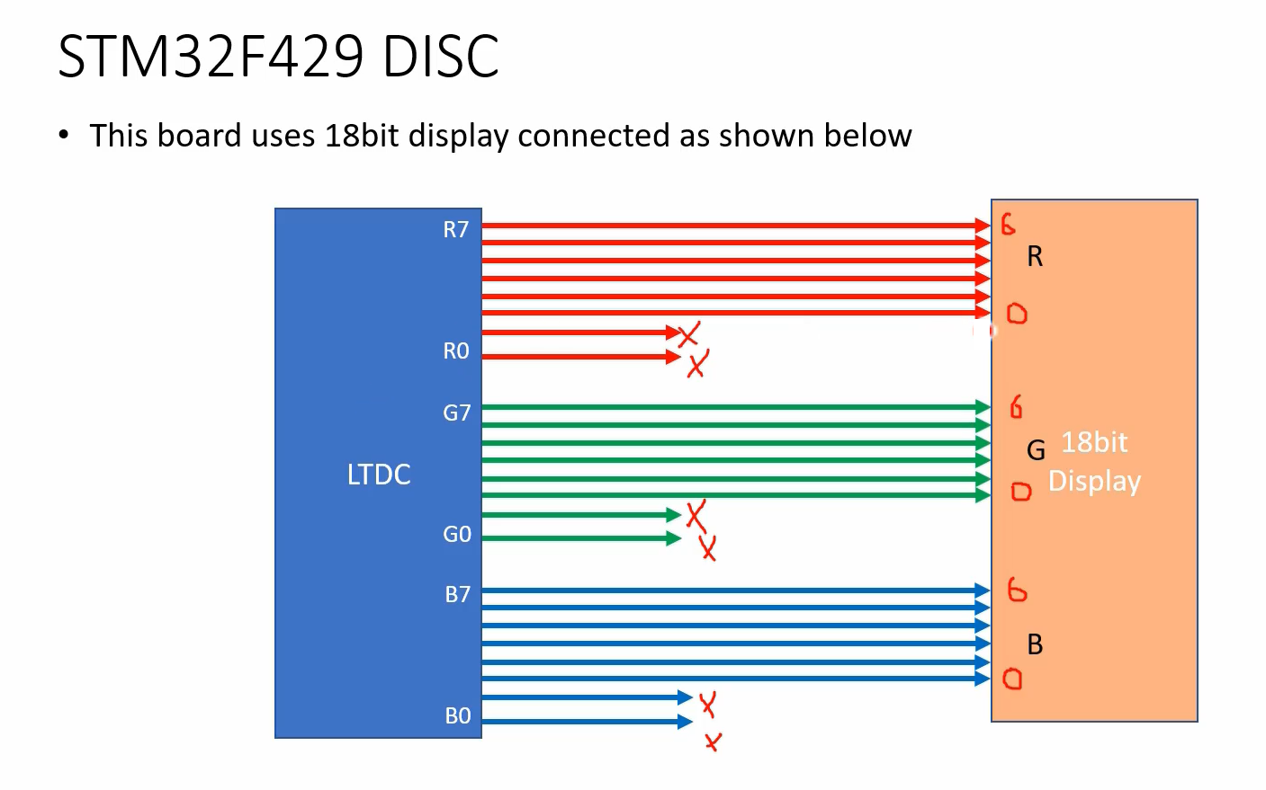
You should always select the most significant lines.
For example, you want to connect an 18-bit display to the LTDC.
LTDC gives you 24 lines, but your display has only 18 data lines. This is the case with the STM32F429 DISC board. The display module, which only exposes 18 lines. So, in that case, the least significant lines are not used. So, you should make use of the most significant lines of the LTDC to connect your display. This is how you should connect.
Because the idea here is not to lose the MSBs.

In the STM32F746ng DISC board, all 24 lines are used, because the display is a 24-bit display.

If it’s a 16-bit display, it gives 5 lines for R, 6 lines for G, and 5 lines for B, then you should connect something like this, as shown in Figure 5.

By using LTDC registers, you can control the LCD-TFT synchronization timings. It is very important. Now, let’s understand this.

First of all, there are some terminologies that you need to understand. Let’s assume that this is the display you want to use in landscape mode, with a width of 320 pixels, which is referred to as the Active Width. It is important to inform the LTDC of the Active Width to ensure proper functionality. Similarly, in our case, the Active Height is 240, which refers to the height of the display. These two pieces of information you have to provide.
And you also program the HSYNC width, HBP, and HFP. So, HBP is the horizontal back porch, and HFP is the horizontal front porch. Together, these components make up the total width, which includes HSW (horizontal sync width), HBP, and HFP. Similarly, the total height includes the active height, VFP (vertical front porch), VPB (vertical back porch), and VSYNC width.”
To obtain the time duration, you need to refer to the datasheet of your LCD driver chip. For example, the ILI9341 datasheet (page 46) contains a table that provides the values of HBP and HFP to be used with the LTDC controller. And these numbers you have to program, we can take the typical column, these numbers you have to program in the LTDC register. So that the LTDC register can generate such signals with the required duration.

Here you can see the horizontal synchronization, that is HSW. And there should be DOTCLK, and HBP is 20, the horizontal address in our case is not 240. If you are using landscape mode, it will be 320. For the portrait, it will be 240, like that. I will show you where to program these values in the LTDC registers.
Let’s do some math.
How to find out the time required to send one frame?
First, you have to calculate the Total width.

Total width(TW)
If I calculate the total width in terms of pixels, then it will be total width = AW+HSW+HBP+HFP pixels.
Total time required to send one line(Tline)
So, the total time required to send one line(Tline) = total width(TW) in pixels multiplied by the time period of a clock or the time required to send one pixel, that is TDOTCLK.
Total lines(TL)
The total lines involved are active height(AH)+VSW+VBP+VFP lines.
Total time required to send 1 frame(Tframe)
Total time required to send one frame(Tframe) = number of lines and time required to send one line. That’s how you can calculate.
In our case, the DOTCLK is 6.25MHz. That’s why, the time period will be 0.16 microseconds. Total width in pixels = 360. The total lines will be 248. That’s why, the time required to send one line is equal to 57.6 microseconds. To send 1 frame you need 14.3 milliseconds with 6.25MHz speed.
This guide outlines how to program synchronization width, back porch numbers, and front porch numbers. Everything you need to know is mentioned in the reference manual, and there are examples provided for further exploration.
Additionally, with the use of LTDC, it is possible to produce a background color. There is a specific register where you can program the RGB values.
In the following article, we will cover LCD pin initialization. You may already be familiar with this process: first, identify the pin and port. Next, go to the GPIO mode register and configure the mode to alternate functionality. Finally, consult the datasheet to determine the appropriate alternate function mode number for the pin’s different alternate modes.
FastBit Embedded Brain Academy Courses
Click here: https://fastbitlab.com/course1


