LTDC background testing
Configuration horizontal synchronization and vertical synchronization timings code.
void LTDC_Init(void)
{
LTDC_TypeDef *pLTDC = LTDC;

REG_SET_BIT(RCC->APB2ENR,RCC_APB2ENR_LTDCEN_Pos);

//Configure horizontal synchronization timings
REG_SET_VAL(pLTDC->SSCR,(BSP_LCD_HSW-1),0xFFFU,LTDC_SSCR_HSW_Pos);
REG_SET_VAL(pLTDC->BPCR,(BSP_LCD_HSW+BSP_LCD_HBP-1),0xFFFU,LTDC_BPCR_AHBP_Pos);
REG_SET_VAL(pLTDC->AWCR,(BSP_LCD_HSW+BSP_LCD_HBP+BSP_LCD_ACTIVE_WIDTH_LANDSCAPE -1),0xFFFU,LTDC_AWCR_AAW_Pos);
uint32_t total_width = BSP_LCD_HSW+BSP_LCD_HBP+BSP_LCD_ACTIVE_WIDTH_LANDSCAPE+BSP_LCD_HFP-1;
REG_SET_VAL(pLTDC->TWCR,total_width,0xFFFU,LTDC_TWCR_TOTALW_Pos);

//configure the vertical synchronization timings
REG_SET_VAL(pLTDC->SSCR,(BSP_LCD_VSW-1),0x7FFU,LTDC_SSCR_VSH_Pos);
REG_SET_VAL(pLTDC->BPCR,(BSP_LCD_VSW+BSP_LCD_VBP-1),0x7FFU,LTDC_BPCR_AVBP_Pos);
REG_SET_VAL(pLTDC->AWCR,(BSP_LCD_VSW+BSP_LCD_VBP+BSP_LCD_ACTIVE_HEIGHT_LANDSCAPE-1),0x7FFU,LTDC_AWCR_AAH_Pos);
uint32_t total_height = BSP_LCD_VSW+BSP_LCD_VBP+BSP_LCD_ACTIVE_HEIGHT_LANDSCAPE+BSP_LCD_VFP-1;
REG_SET_VAL(pLTDC->TWCR,total_height,0x7FFU,LTDC_TWCR_TOTALH_Pos);
Configure the background color RED
REG_SET_VAL(pLTDC->BCCR, 0xFF0000U, 0xFFFFFFU, LTDC_BCCR_BCBLUE_Pos);
The code sets the LTDC’s Background Color Control Register (BCCR) to display the color red. The BCCR is a register that determines the background color of the display when no image is present.
The REG_SET_VAL function appears to be a macro or a function that sets a specific bit range within a register to a given value.
In this case, the REG_SET_VAL function sets the bits corresponding to the red color component (0xFF0000U) to 1 and sets the bits corresponding to the blue and green color components (0xFFFFFFU) to 0. This effectively sets the background color to solid red.
Enable the LTDC peripheral
After that, you enable the LTDC peripheral:– REG_SET_BIT(pLTDC->GCR, LTDC_GCR_LTDCEN_Pos);
Once you execute this step, you must see the Red color on the display.
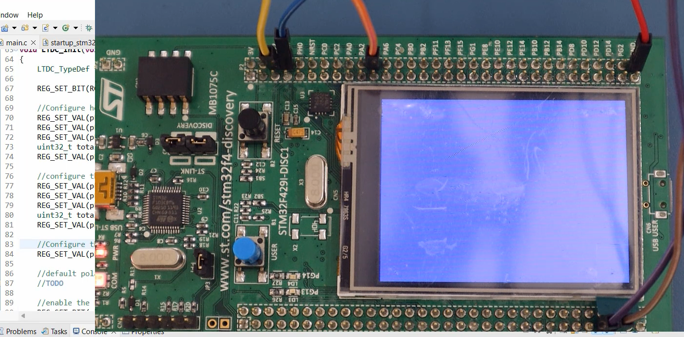
Test the code on the hardware. As you can see, the display shows a Red color, but it doesn’t occupy the whole screen, leaving some gaps (Figure 1).
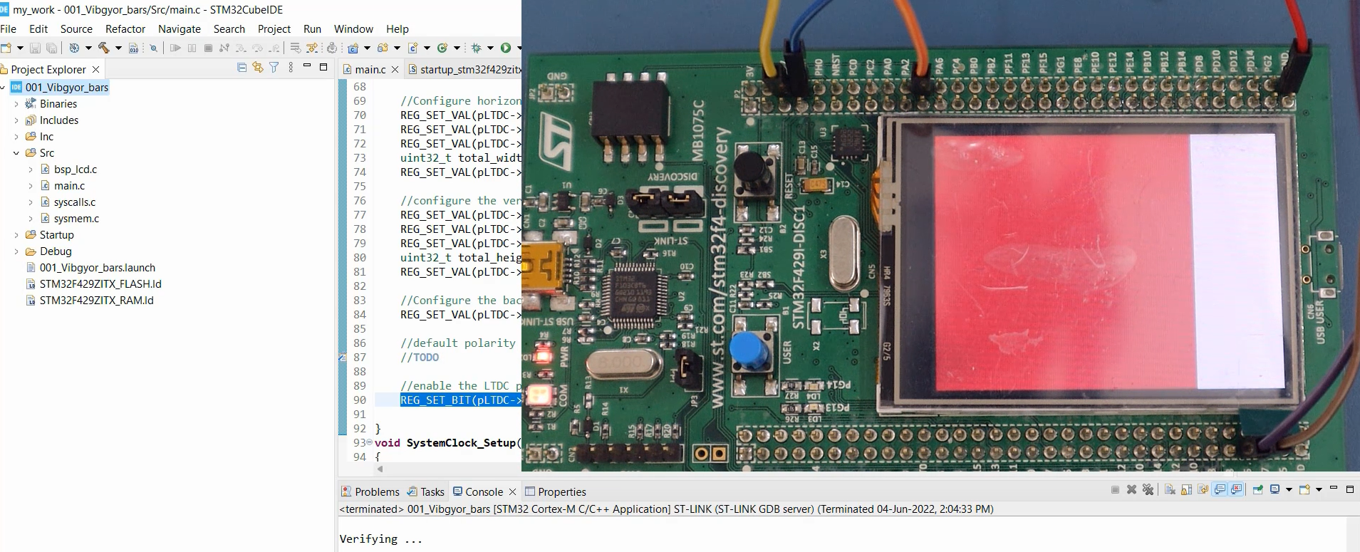
Let me explain the reason for that. Here, we will change BSP_LCD_ACTIVE_HEIGHT_LANDSCAPE to BSP_LCD_ACTIVE_WIDTH_LANDSCAPE. This change needs to be made in both horizontal and vertical synchronization timings.
//Configure horizontal synchronization timings
REG_SET_VAL(pLTDC->SSCR,(BSP_LCD_HSW-1),0xFFFU,LTDC_SSCR_HSW_Pos);
REG_SET_VAL(pLTDC->BPCR,(BSP_LCD_HSW+BSP_LCD_HBP-1),0xFFFU,LTDC_BPCR_AHBP_Pos);
REG_SET_VAL(pLTDC->AWCR,(BSP_LCD_HSW+BSP_LCD_HBP+BSP_LCD_ACTIVE_WIDTH_LANDSCAPE -1),0xFFFU,LTDC_AWCR_AAW_Pos);
uint32_t total_width = BSP_LCD_HSW+BSP_LCD_HBP+BSP_LCD_ACTIVE_WIDTH_LANDSCAPE+BSP_LCD_HFP-1;
REG_SET_VAL(pLTDC->TWCR,total_width,0xFFFU,LTDC_TWCR_TOTALW_Pos);

//configure the vertical synchronization timings
REG_SET_VAL(pLTDC->SSCR,(BSP_LCD_VSW-1),0x7FFU,LTDC_SSCR_VSH_Pos);
REG_SET_VAL(pLTDC->BPCR,(BSP_LCD_VSW+BSP_LCD_VBP-1),0x7FFU,LTDC_BPCR_AVBP_Pos);
REG_SET_VAL(pLTDC->AWCR,(BSP_LCD_VSW+BSP_LCD_VBP+BSP_LCD_ACTIVE_WIDTH_LANDSCAPE-1),0x7FFU,LTDC_AWCR_AAH_Pos);
uint32_t total_height = BSP_LCD_VSW+BSP_LCD_VBP+BSP_LCD_ACTIVE_WIDTH_LANDSCAPE+BSP_LCD_VFP-1;
REG_SET_VAL(pLTDC->TWCR,total_height,0x7FFU,LTDC_TWCR_TOTALH_Pos);
Once you make these changes, test the program. Then you can get the proper output(Figure 2).
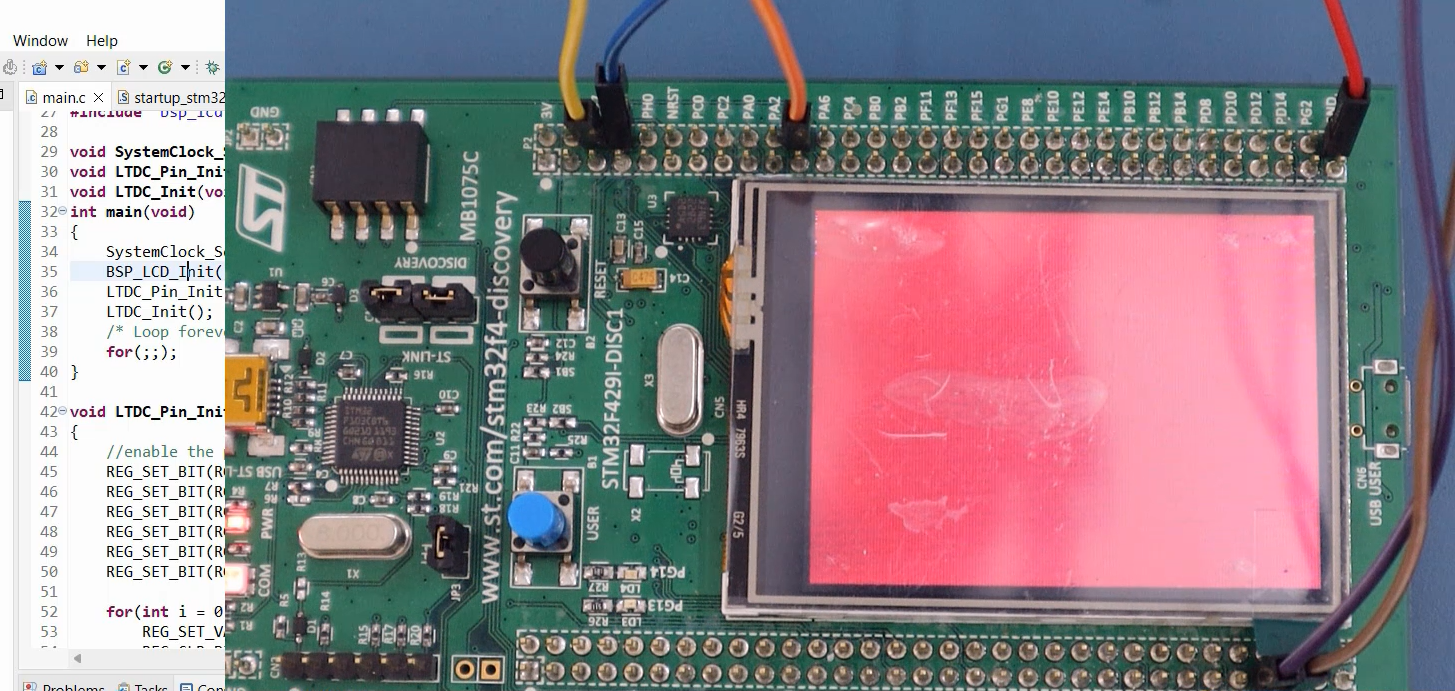
You can also try changing some values to see different colors. For instance, you can change the red value (0XFF0000U) to produce the Blue color (0x0000FFU).
//Configure the background color(BLUE)
REG_SET_VAL(pLTDC->BCCR,0x0000FFU,0xFFFFFFU,LTDC_BCCR_BCBLUE_Pos);
As shown in Figure 3, the output now produces the Blue color.
FastBit Embedded Brain Academy Courses
Click here: https://fastbitlab.com/course1

