Pixel writing in the case of STM32F407x+ External LCD
Pixel writing in the case of STM32F407x + external LCD
There are 2 methods.
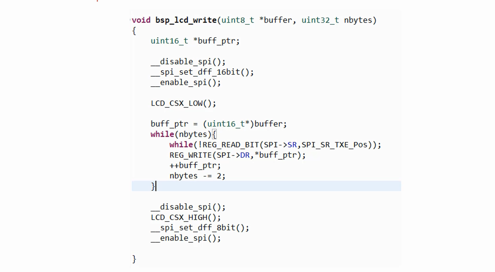
- Non-DMA based data write or pixel write over SPI(processor involved)
- Check the function void bsp_lcd_write(uint8_t *buffer, uint32_t nbytes) in bsp_lcd.c.
- DMA based data write over SPI.
- Check the function void bsp_lcd_write_dma(uint32_t src_addr, uint32_t nbytes) in bsp_lcd.c.
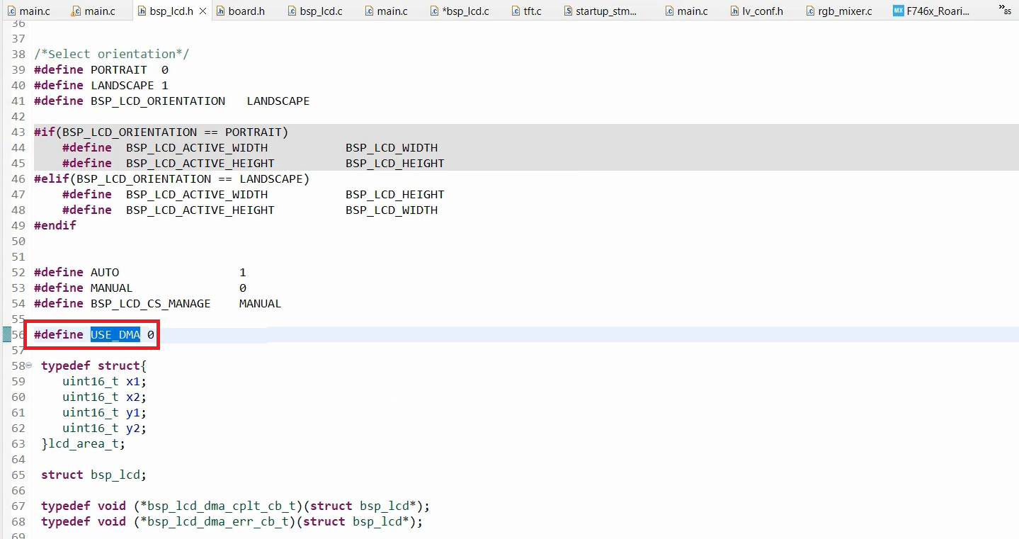
In the bsp_lcd.h, there is a flag called USE_DMA (Figure 1). If you enable that flag, then the pixel writing will happen over DMA.
Pixel buffer
- In the case of STM32F407x+external LCD, you cannot use a screen sized frame buffer like in the case of STM32F429 disc board.
- bsp_lcd.c uses non screen sized buffer of 10KB (Draw buffer)
Let’s understand how pixel writing occurs in the case of a non-screen-sized buffer of 10KB (draw buffer).
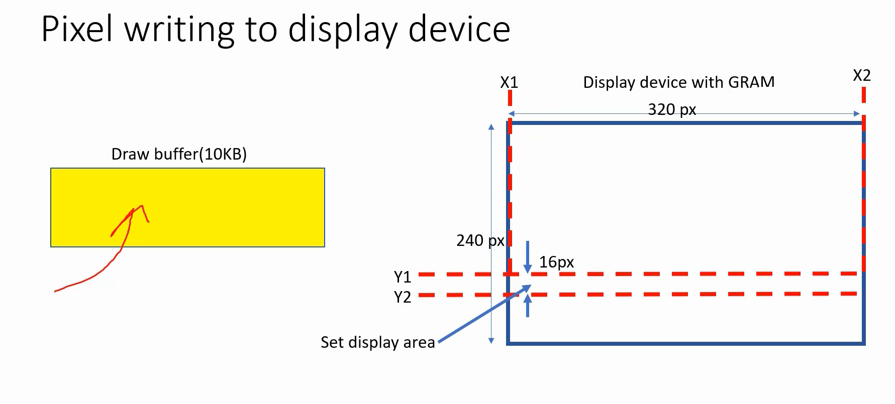
Take a look at Figure 2, where there is a draw buffer of 10 kilobytes and a display device with built-in graphics RAM (GRAM). You fill this draw buffer with pixel data that represents the color yellow. First, you need to set the display area by sending commands to the display device. Essentially, you have to send the X1 and X2 numbers, as well as the Y1 and Y2 numbers, which means you have to provide the coordinates to the display device. There are specific commands to accomplish this.
After that, you need to perform LCD WRITE (refer to Figure 3), which can be done using either DMA or non-DMA based methods. All the pixel data will be written to the graphics RAM of the display device and displayed according to your display area setup.
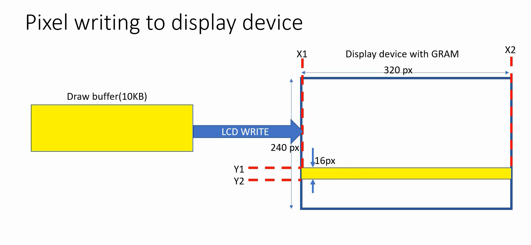
Figure 4 illustrates the process of setting the display area. To accomplish this, you need to send two commands to the LCD. The first command is CASET, which stands for column address set command, while the second one is RASET, also known as the row address set command. Both CASET and RASET can also be referred to as page address set commands.
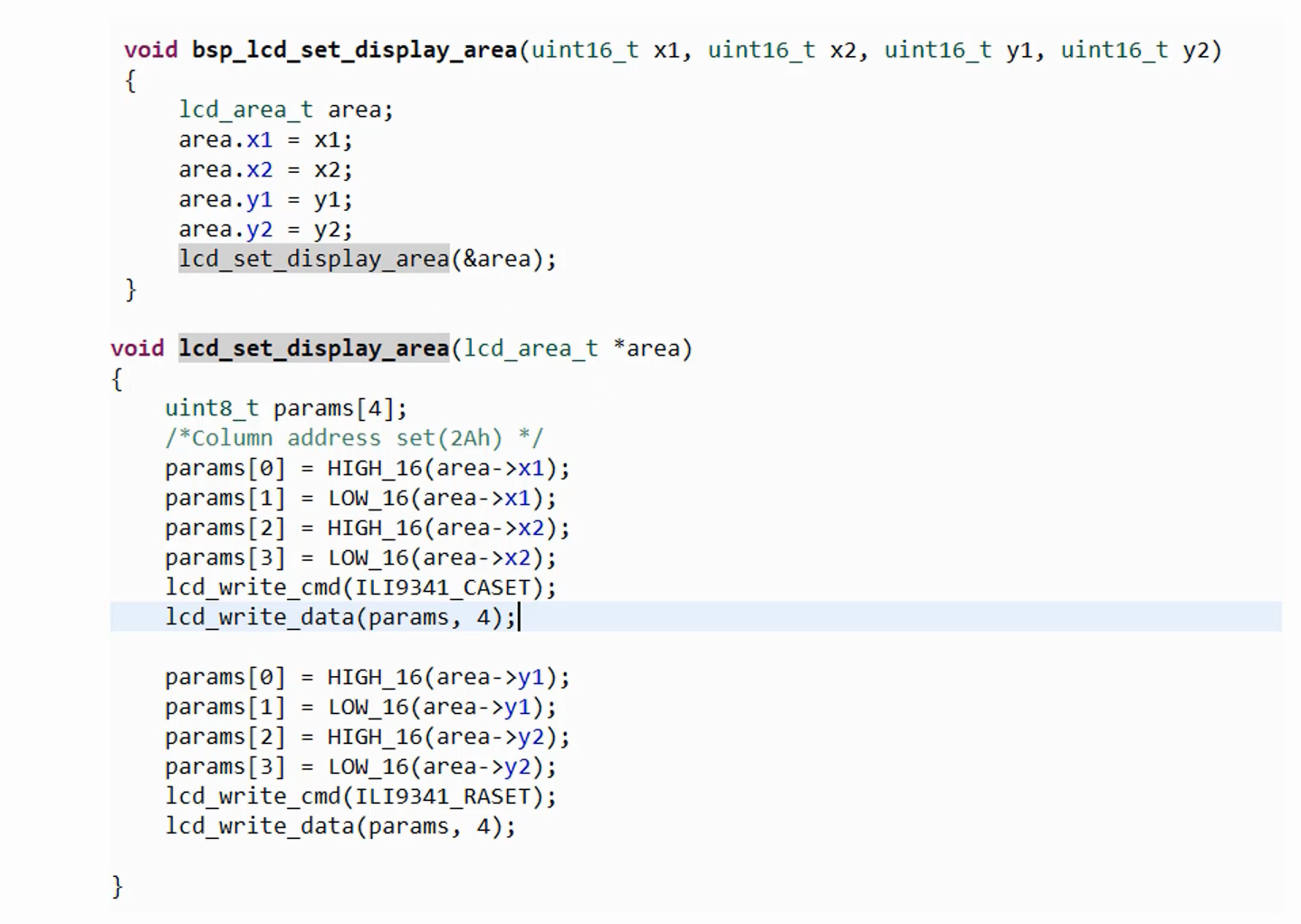
For RASET command you have to mention the Y numbers. Similarly, for the CASET command, you need to mention the X coordinates. To gain a better understanding of these commands, please refer to the ILI9341 datasheet. These functions can be found in bsp_lcd.c.
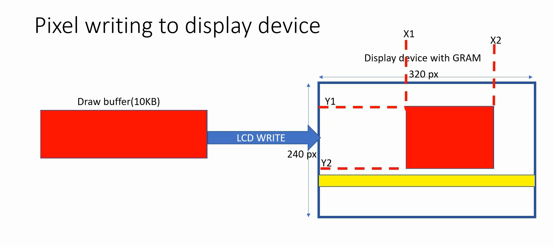
You can draw a red rectangle on the display area, as illustrated in Figure 5. To accomplish this, utilize the same draw buffer filled with pixel data representing the color red. The display area can be set by sending X1, X2, Y1, and Y2 coordinates using the CASET and RASET commands.
Once the display area is set, then you can proceed with the LCD WRITE operation. It is important to note that the previous LCD Write operation will not be affected due to the presence of built-in graphics RAM. The graphics data will persist in the RAM until the display device is reset.
If you want to paint or set the background color for the display, then you have to repeatedly send these draw buffers like this(Figure 6). That means, first you have to fully flush the draw buffer and then change Y1 and Y2, and then again flush and then again change Y1 and Y2, and again flush, like that.
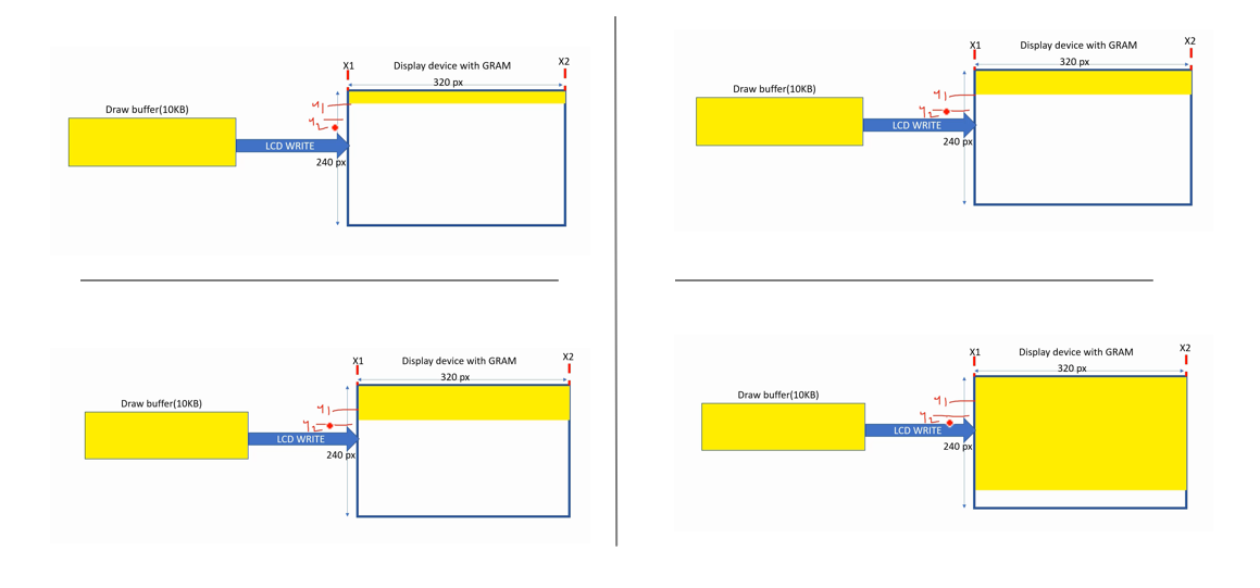
That’s how you paint the display.
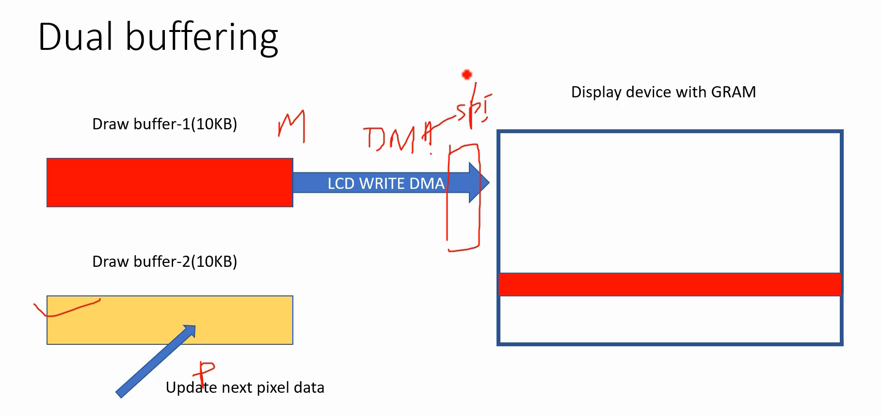
You can also use a dual buffering, where flushing and pixel value updates occur concurrently.
In this case, you have to use the DMA to flush the contents of the draw buffer to the display device.
Take a look at Figure 7. There is a draw buffer, referred to as Draw Buffer-1, with a size of 10 kilobytes. And the DMA flushing is occurring towards the display. In this scenario, you can use another draw buffer to update the next pixel data. This means that the application doesn’t need to wait for the flush to complete before updating the next pixel data. The update can happen in parallel using a different buffer because the DMA handles it. Likewise, the processor can simultaneously update the next pixel data in a separate buffer.
By the way, this DMA is memory to peripheral transfer. Peripheral in this case is SPI. It happens over SPI. So, it’s a memory to peripheral transfer.
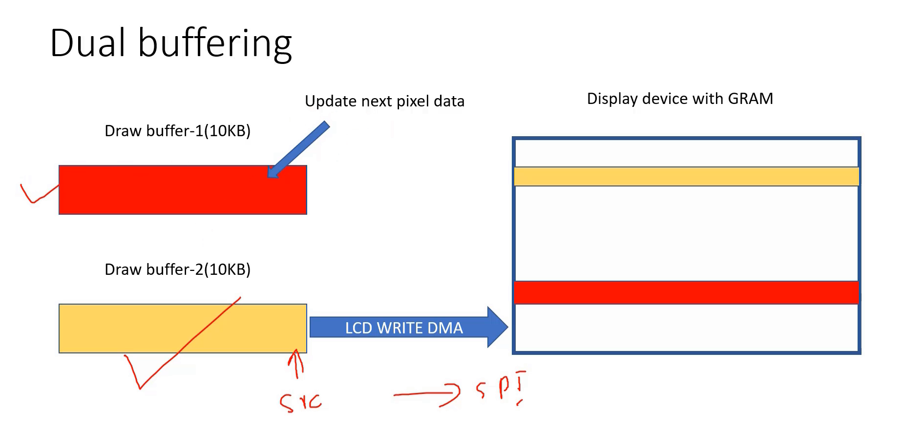
To initiate the DMA transaction, you have to provide the Draw buffer address as the source address, and the destination address will be the SPI Data register. This means that the DMA direction is from memory to peripheral. And when the application updates Draw buffer-2, it can be utilized as a source address. Consequently, you can trigger another DMA transaction from this source address to the destination, which is the SPI. Moreover, the application can utilize Draw buffer-1 to update the subsequent pixel data, as shown in Figure 8.
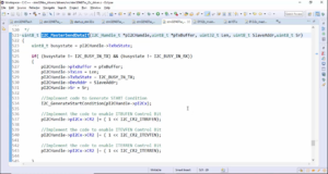
Here is a code to write data to the BSP without using DMA.
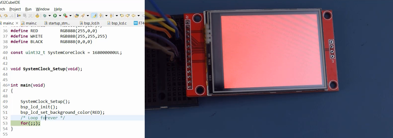
Testing background color STM32F407X+external LCD
If you want to set the background color for an external LCD connected to the STM32F407 Discovery board, you can easily achieve this by utilizing the BSP function bsp_lcd_set_background_color. Simply set the color to RED.
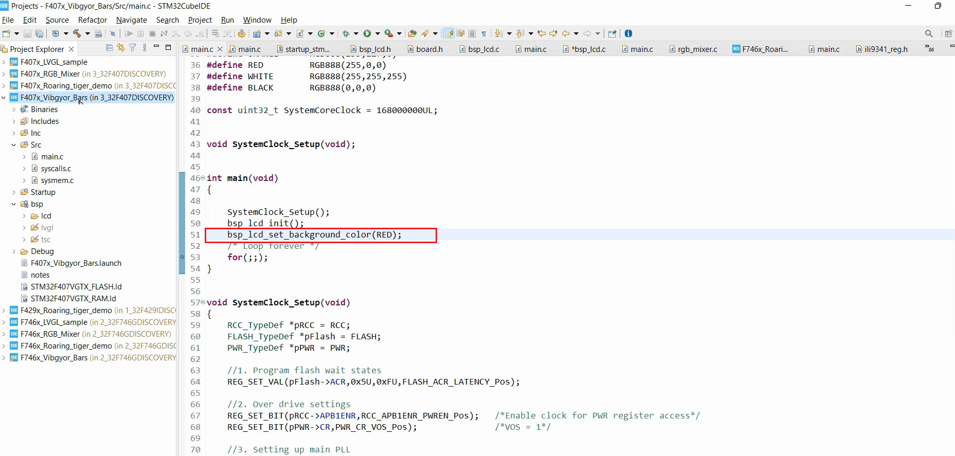
Once you have made the necessary changes, proceed to compile the code and upload it to the hardware. After running the program, you will notice that the screen is now painted in the color red, as depicted in Figure 11.
FastBit Embedded Brain Academy Courses
https://fastbitlab.com/course1