Understanding UART pins
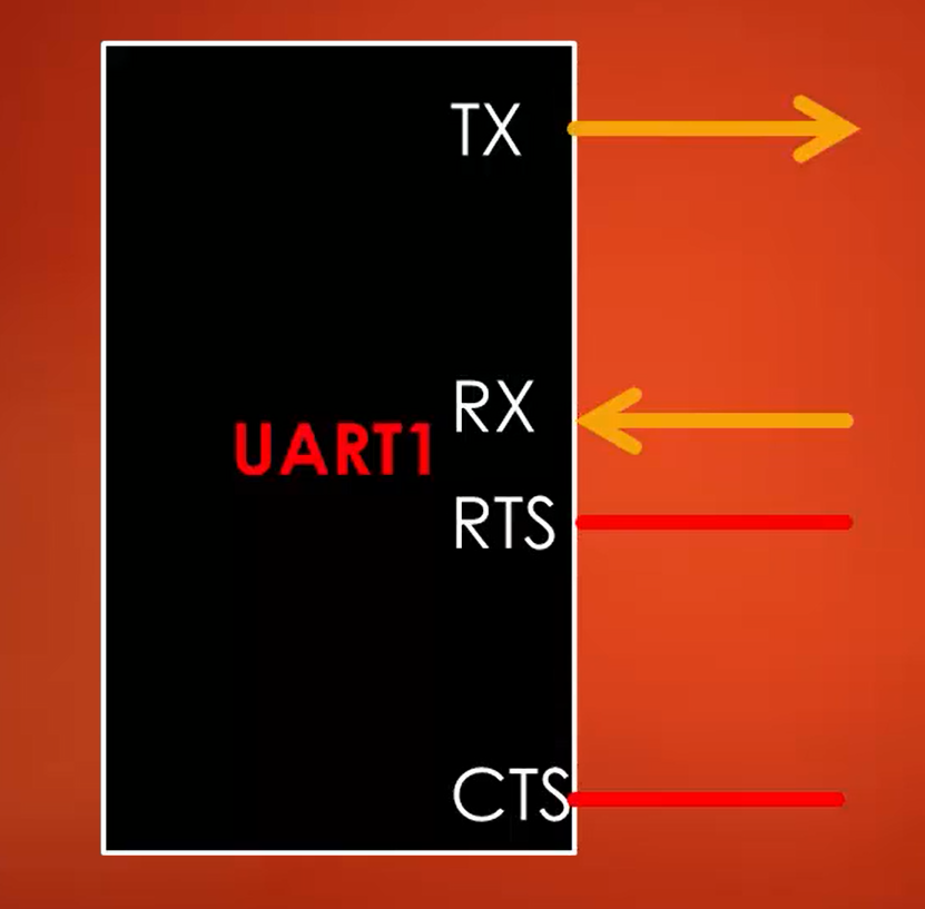
UART bidirectional communication requires at least 2 pins when hardware flow control is not used.
One is TX, and another one is RX (Figure 1).
We receive data into the UART module over the RX pin, and we transmit data out of the UART module over TX. If you are not transmitting anything, then the TX line will be held high, which is the idle state of the line.
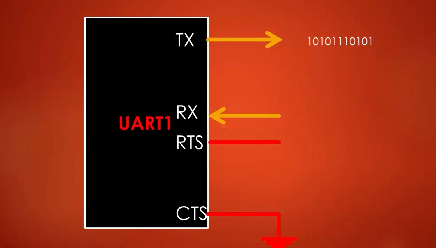
In order to receive data on the RX line, the UART module continuously samples the RX line to detect the start bit of the frame. Once the start bit is detected, the frame reception kicks in on the RX line until it again detects the idle line.
RTS and CTS lines shown in Figure 1 are the pins that are required when you use hardware flow control.
CTS stands for Clear to Send. It’s an active low pin. When hardware flow control is used, the data transmission on the TX line happens, and the UART module will send the data out of the TX line, as shown in Figure 2, only if the CTS pin is pulled low. Otherwise, the data transmission will be held until this pin is pulled to low.
CTS pin has to be pulled to low by another device to enable the data transmission.
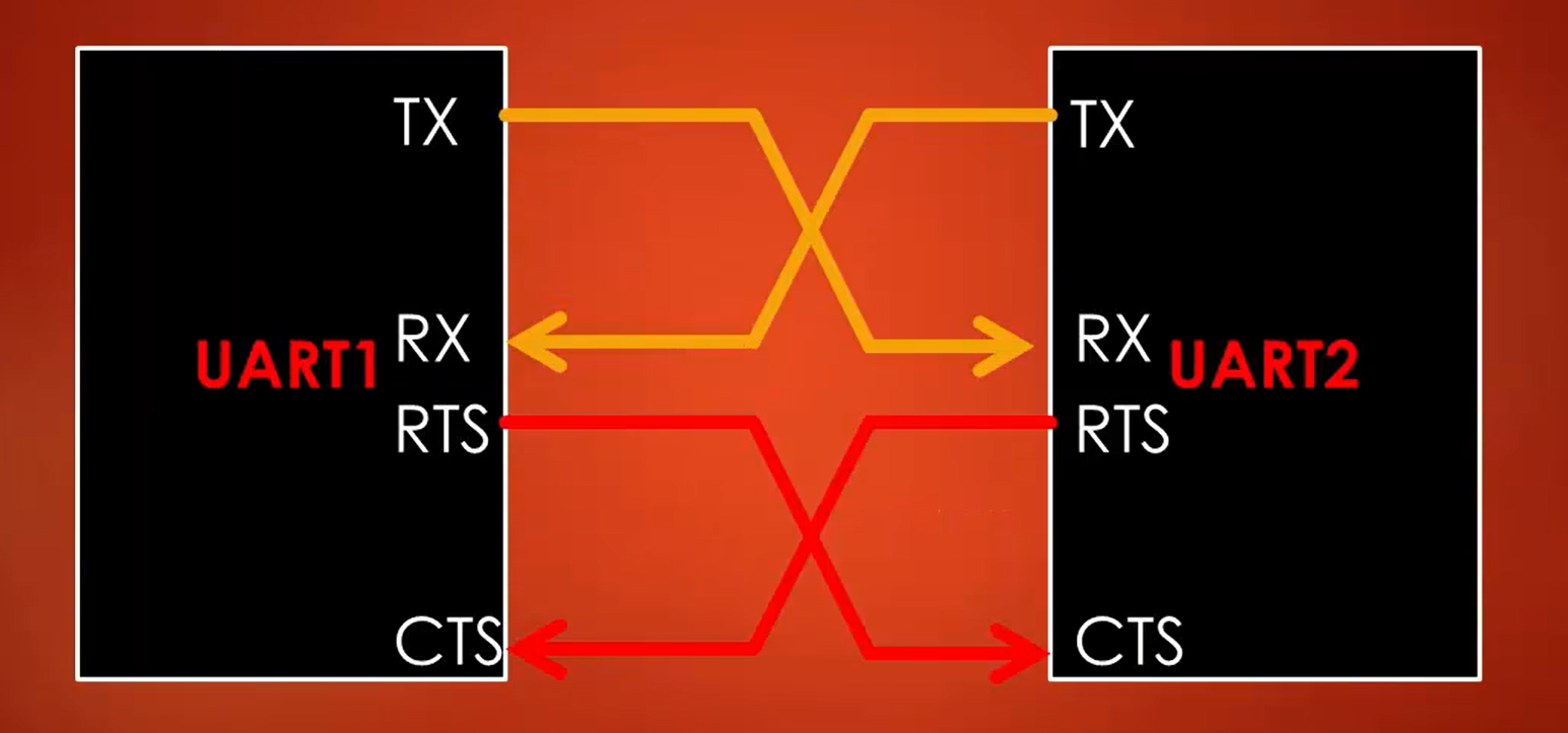
RTS stands for Request to Send. It is also an active low pin. The device uses this line to inform the other device that it needs data. Between two devices, the RTS and CTS signals are connected, as shown in Figure 3.
RTS of one device is connected to the CTS of another device. When the first device wants the data from the second device, then the RTS will be asserted low in the first device, which causes the second device to transmit the data on the TX line by pulling its CTS to low.
In the following article, let’s see UART frame formats.
FastBit Embedded Brain Academy Courses
Click here: https://fastbitlab.com/course1


