Synchronization bits
Synchronization Bits in Serial Communication
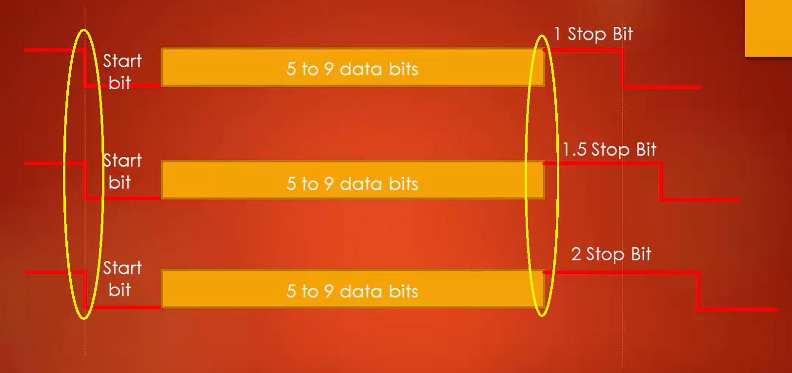
The synchronization bits are two or three special bits transferred with each chunk of data.
They are the start bit and the stop bits.
These bits mark the beginning and end of a packet (Figure 1).
There is always only one start bit, but the number of stop bits is configurable to either 1 or 2.
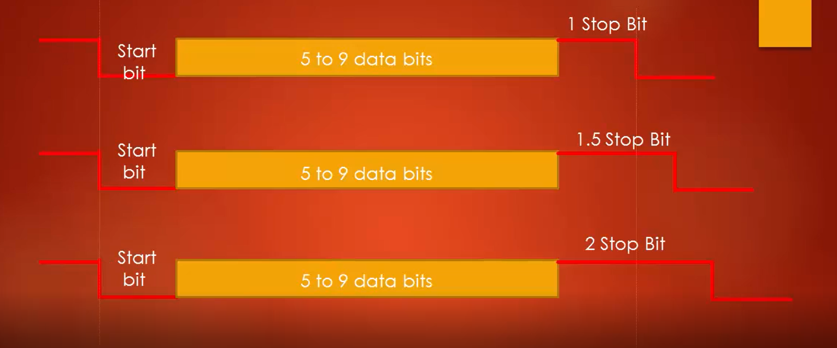
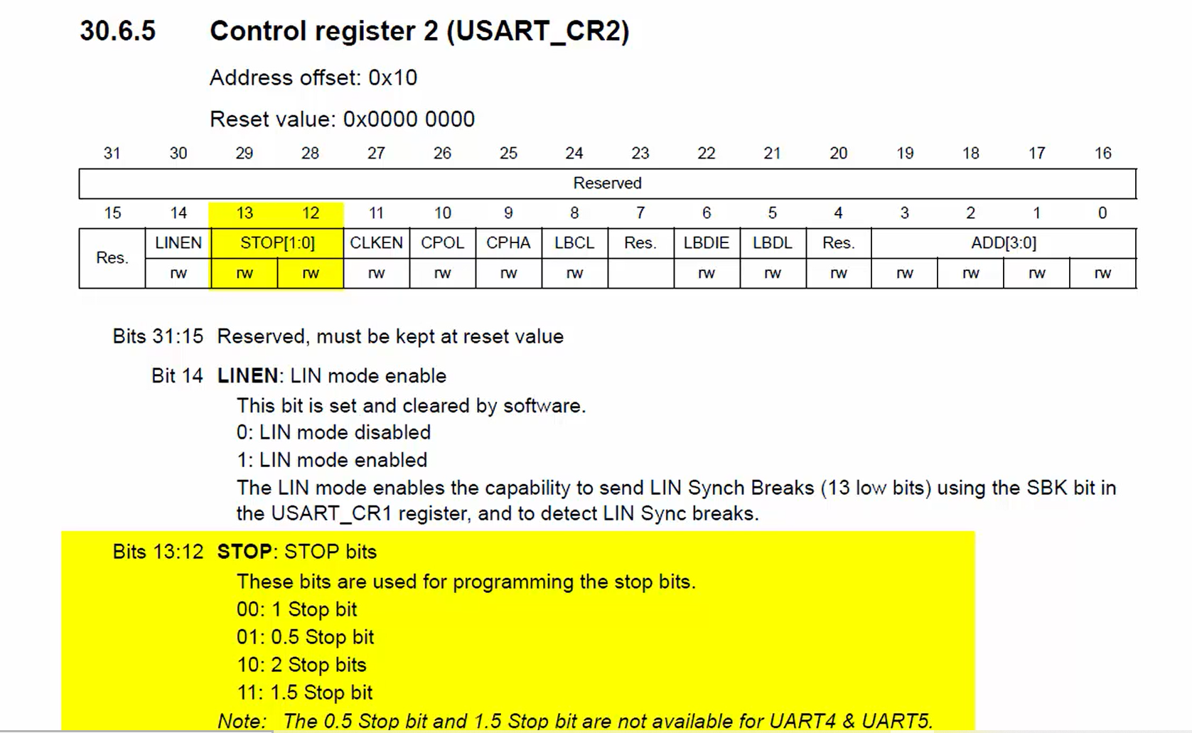
In the STM32F4xx microcontroller, you can even choose 105 stop bits. That means one-and-a-half-bit duration. The stop bit in the register USART control register 2 (Figure 2) selects the number of stop bits to be inserted by the transmitter. Typically, we use one stop bit in most of the applications but if your baud rate is very high, say in terms of megabits per second, then you may think of inserting two stop bits.
The start bit is always indicated by an idle data line (Figure 3) going from high to low. While the stop bit will transition back to the idle state by holding the line at high.
In the following article, let’s see UART Parity.
FastBit Embedded Brain Academy Courses
Click here: https://fastbitlab.com/course1