UART peripheral clock
In the previous article, let’s explored the UART functional block. In this article, let’s discuss about the peripheral clock of the USART peripheral.
Now let’s see on which bus the USART hardware is connected. As you can see in Figure 1, USART1 and USART6 are connected to the bus APB2, which can run at a maximum of 84MHz. So ideally, our USART1 and USART6 should be able to run at 84MHz in this case.
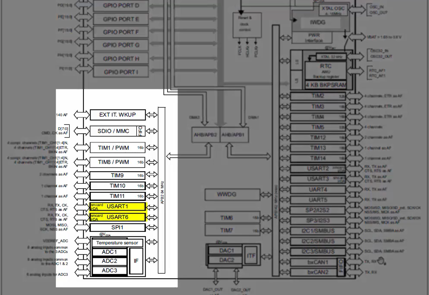
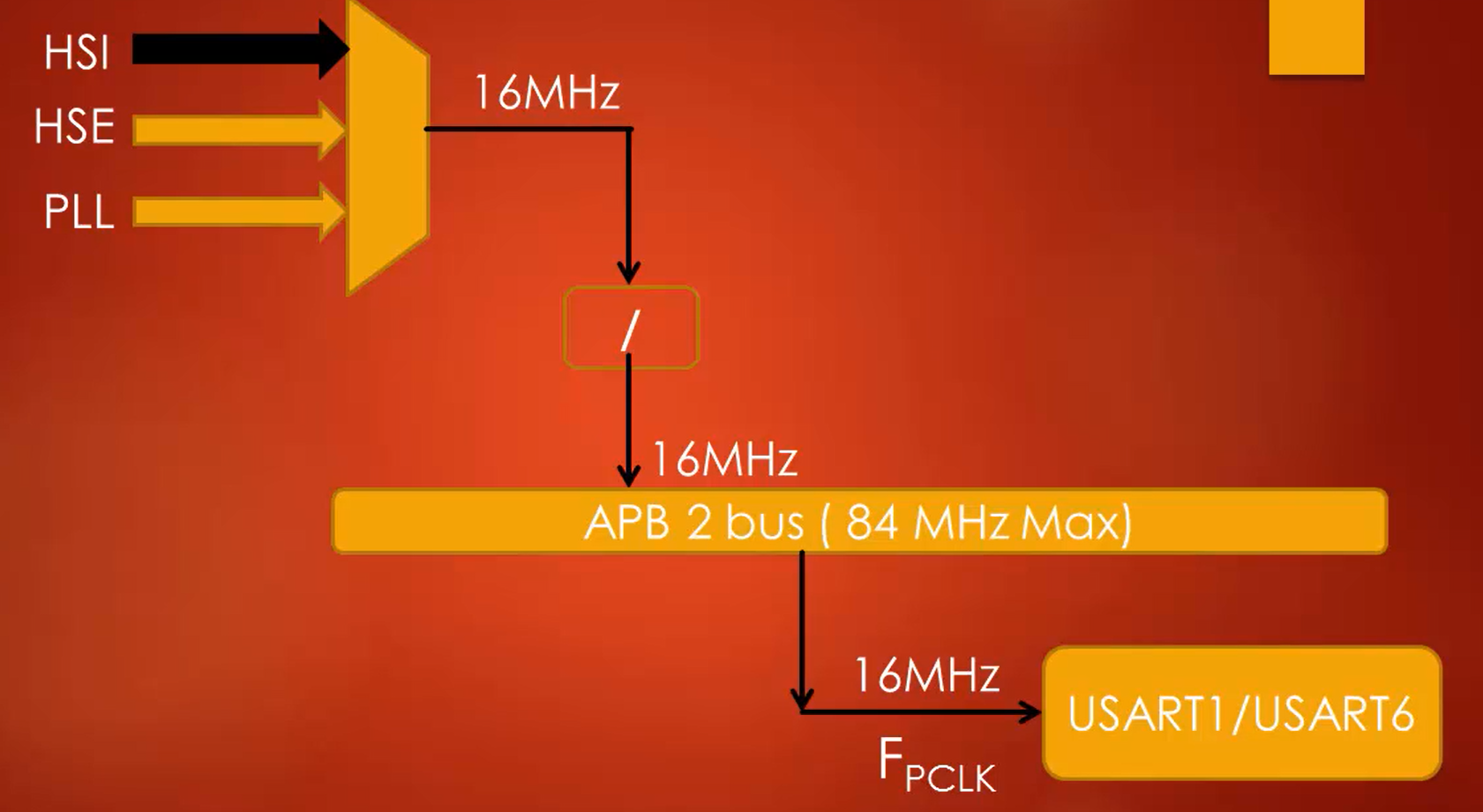
But when the microcontroller is powered by an internal RC oscillator of 16MHz, as shown in Figure 2, the maximum peripheral clock your USART hardware gets is 16MHz since all the bus interfaces will be running at that speed.
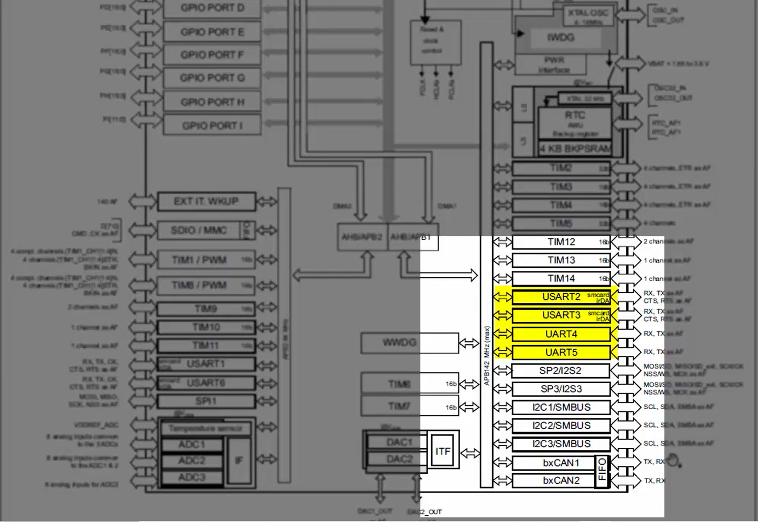
Similarly, USART2, USART3, UART4, and UART5 are connected to the APB1 bus (Figure 3), whose maximum frequency is 42MHz. So, the conclusion is that the USART1 and USART6 have the potential to run at higher frequencies than USART2, USART3, UART4, and UART5 since they are on different buses.
In our lab session, since we run our microcontroller using an internal RC oscillator, all USART hardware runs with a peripheral frequency of 16MHz. Remember that the peripheral frequency will be used by the baud rate generation block of the USART peripheral to produce different baud rates.
In the following article, let’s understand the UART Transmitter.
FastBit Embedded Brain Academy Courses
Click here: https://fastbitlab.com/course1

