USART Driver API: Send data
In this article, let’s understand USART_SendDataAPI used to send data from the USART peripheral to the external world.
Steps of implementation:
1. First of all, there is a for loop that is to loop over until the “Len” number of bytes are transferred.

2. Since it is a serial communication peripheral just like I2C or SPI, it also has TXE in the SR register and you have to wait until the TXE is set (Figure 2), which is an indication to make sure that the transmit data register (TDR) in the peripheral is empty.

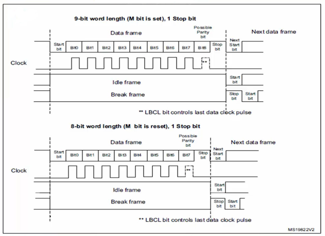
3. After that, you have to make the decision whether you are transmitting 9 bits in a frame or 8 bits in a frame. Because if you take a look into the word length programming diagram of the reference manual (Figure 3), there are two options for control bit M.
- If control bit M is 1, then a frame contains 9 bits of data. So, if M=1, then 9 bits will be transferred, out of which 8 bits will be of user data, and 1 bit will be parity bit if parity is enabled. The hardware will attach the parity bit to the last bit position automatically. If the parity bit is disabled, then all 9 bits will be of user data.
- If M=0, then a frame contains only 8 bits. That means, if M=0, then 8 bits will be transferred, out of which 7 bits will be of user data and 1 bit will be parity bit if parity is enabled. Otherwise, all 8 bits are of user data.
Based on the above conditions, you have to code. Therefore, it is first checked whether you are doing 9-bit data transmission or 8-bit data transmission, as shown in Figure 4.
If the word length = 9 bits, then you have to load the 9 bits into the data register (DR). That’s why the 9 bits are extracted, as shown in Figure 4, by using the masking factor 0x01FF. So, 0x01FF is used to mask out 9 bits from the 16-bit data. That’s why the pTxBuffer is type casted to extract 2 bytes of data, in which only 9 bits are loaded into the data register.


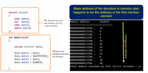
If parity is disabled, then all 9 bits will be of user data. It’s like transferring 2 bytes since we need two bytes to hold 9 bits. That’s why the buffer address is incremented by 2, as shown in Figure 5.

If parity is used in this transfer, the 8 bits of user data will be sent, and the 9 bit is replaced with the parity bit by the hardware. Therefore, here only 8 bits (1 byte) are enough to send the data, and now you have to increment the buffer byte by byte, as shown in Figure 6.

If the word length is 8 bits, then you have code, as shown in Figure 7. Just load a byte into the DR and then increment the buffer.

4. Wait until the transmission complete is set (Figure 8), which ensures that all the bits are successfully transferred from the USART to the external world. After this, you can turn off the transmit engine or put the peripheral into low power mode or whatever you can do. But before that, make sure that TC is set.

In the following article, let’s see USART oversampling.
FastBit Embedded Brain Academy Courses
Click here: https://fastbitlab.com/course1


