USART oversampling
Before understanding the baud rate generation, let’s first understand about USART oversampling, and there is a control bit for configuring the oversampling.
What is oversampling?
Oversampling is a technique, which is used by the receive engine of the USART peripheral.
The receiver of the USART peripheral implements different user-configurable oversampling techniques (except in synchronous mode) for data recovery by discriminating between the valid incoming data and noise.
Basically, the oversampling technique talks about the sampling frequency of the USART peripheral’s receive engine to recover the data coming on the RX line of the USART.
The oversampling method can be selected by programming the OVER8 bit in the USART_CR1 register and can be either 16 or 8 times the baud rate clock. That means you can configure the sampling rate either 16 or 8 times the baud rate clock. The configurable oversampling method by 16 or by 8 to give flexibility between speed and clock tolerance.
Two cases of oversampling:
The first diagram in Figure 1 is the data sampling when oversampling by 16 is used, and the second diagram is the data sampling when oversampling by 8 is used.
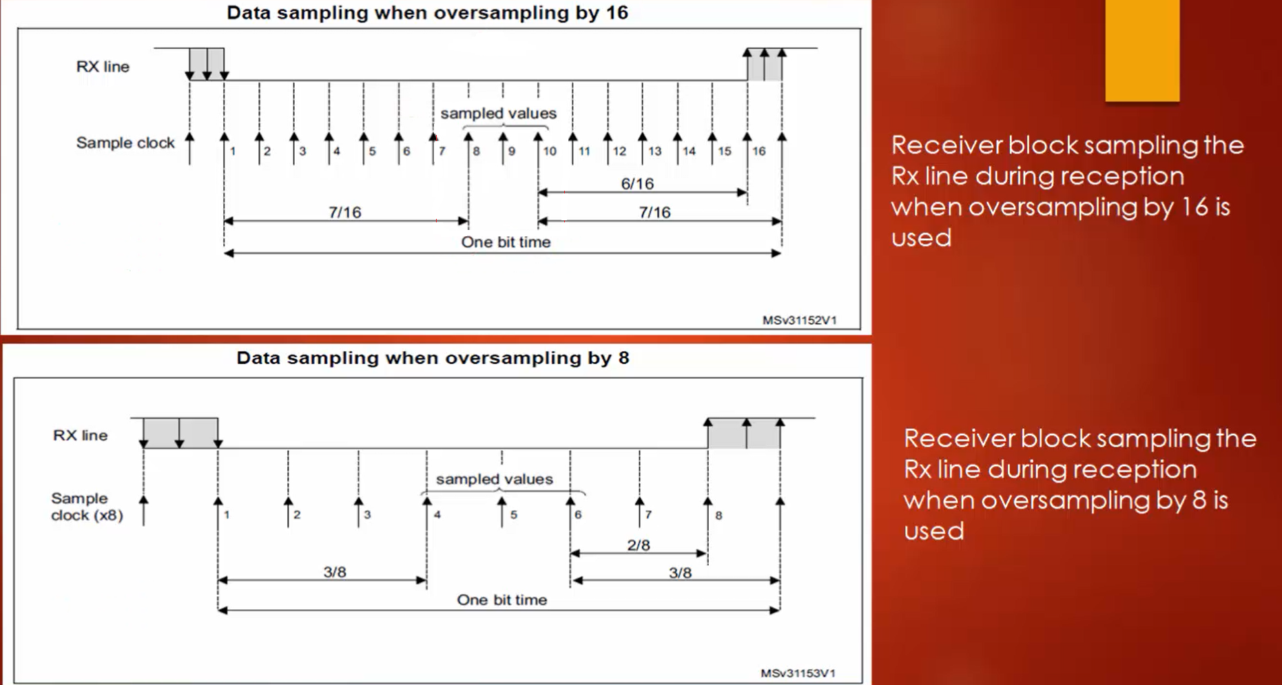
When oversampling by 16 is used, the receiver engine samples a one-bit period 16 times. That means it takes 16 samples to understand that bit. A bit can be either 0 or 1.
To understand whether the bit is 1 or 0, a receiver engine takes 16 samples, in which the samples taken at the position of 8, 9, and 10 will be analyzed.
If oversampling by 8 is used, then the receiver engine takes 8 samples in a 1-bit period or 1-bit time, and the samples taken at the position of 4, 5, and 6 (or sampled values) will be compared to understand whether this bit is 1 or 0. By using these sampled values, the USART engine understands whether it is valid data or noise.
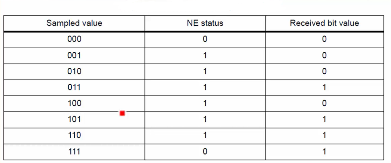
For example, Look at Figure 2. If all sampled values are 000, then the receiver engine considers that as bit value 0, and if the sampled values are all 111, then the receiver engine confirms that the received bit value is 1. But if you see all the remaining sampled values in Figure 2, they make the noise error (NE) as 1. So, the noise error will be triggered. If any of the sampled values fall under the values that trigger NE, the noise detection flag will be set in the status register, and then the application may discard the byte, or it may consider the byte based on the application logic. But the receiver engine sets the noise detection flag if the sample values are not proper.
When is the noise detected in a frame?
The NF flag bit is set by the hardware when noise is detected on the received frame. The invalid data is transferred from the shift register to the USART_DR register. The application may consider or discard the frame based on application logic.
When the NF flag is set, it means the receiver is saying to you that there was a problem with the reception, and the data in the data register may be invalid, and the application may take the decision according to its logic.
How to select the proper oversampling method?
If you select oversampling by 8 (OVER8=1), then you can achieve a maximum baud rate up to FPCLK/8, but in this case, the maximum receiver tolerance to clock deviation is reduced.
The advantage of using oversampling by 8 is, it is possible to achieve higher baud rates.
There are several reasons for the clock deviation as follows:
- The type of clock generation circuit you have used in your microcontroller: The clock source may be crystal, it may be from RC oscillator, or it may be from PLL.
For example, if you are using an RC oscillator, then clock deviation is more since the RC oscillators heavily depend on temperature variation. In such a case, the receiver may fail and can generate a noise error for each byte received from the USART peripheral. That means a receiver cannot tolerate more clock deviation if you use oversampling by 8.
If you select oversampling by 16 (OVER8=0), then you can achieve a maximum baud rate up to FPCLK/16, which is lesser than what you get from oversampling by 8. But in this case, the maximum receiver tolerance to clock deviation is increased. That means even if there is a clock deviation, the tolerance of the receiver will be increased.
The thumb rule is: If you are using your USART application in a very noisy environment, then use oversampling by 16. If your environment is noise-free, then you can use oversampling by 8.
In the following article, let’s see USART baud rate calculation.
FastBit Embedded Brain Academy Courses
Click here: https://fastbitlab.com/course1