Flowchart for detecting key press events in the keypad
In this article, let’s explore the flowchart for detecting key press events in the keypad.
For this exercise I’ll be considering PD8, PD9, PD10, and PD11, these are column GPIOs; PD0 to PD3, these row GPIOs.
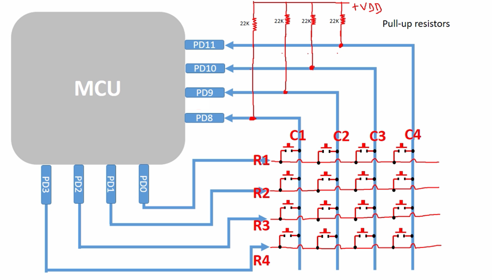
So, if you are using the STM32 discovery board, then you can definitely use this IOs, because these are free. If you are using some other board, please investigate what are the IOs you can use with this exercise. You need 8 free IOs. So, you have to investigate your board using the user manual of your board.
Detecting key press event in Keypad Flowchart
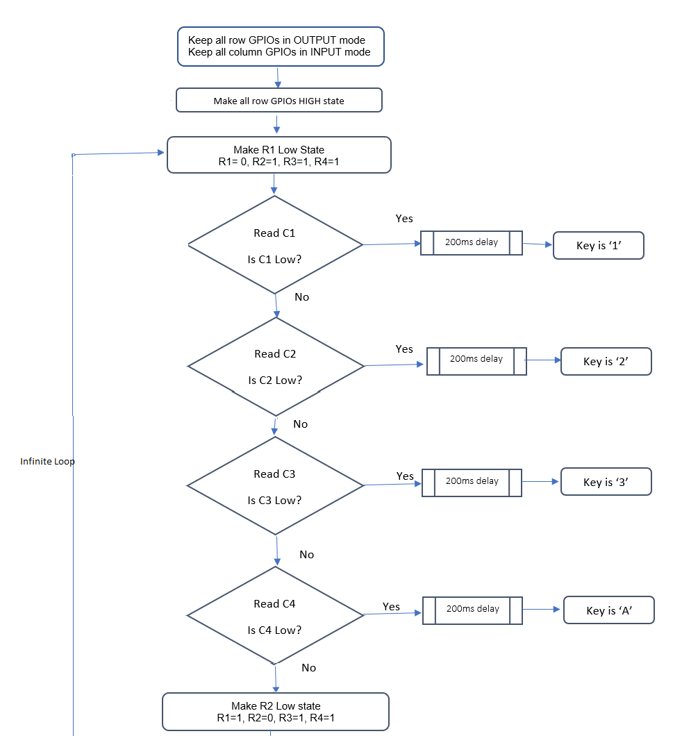
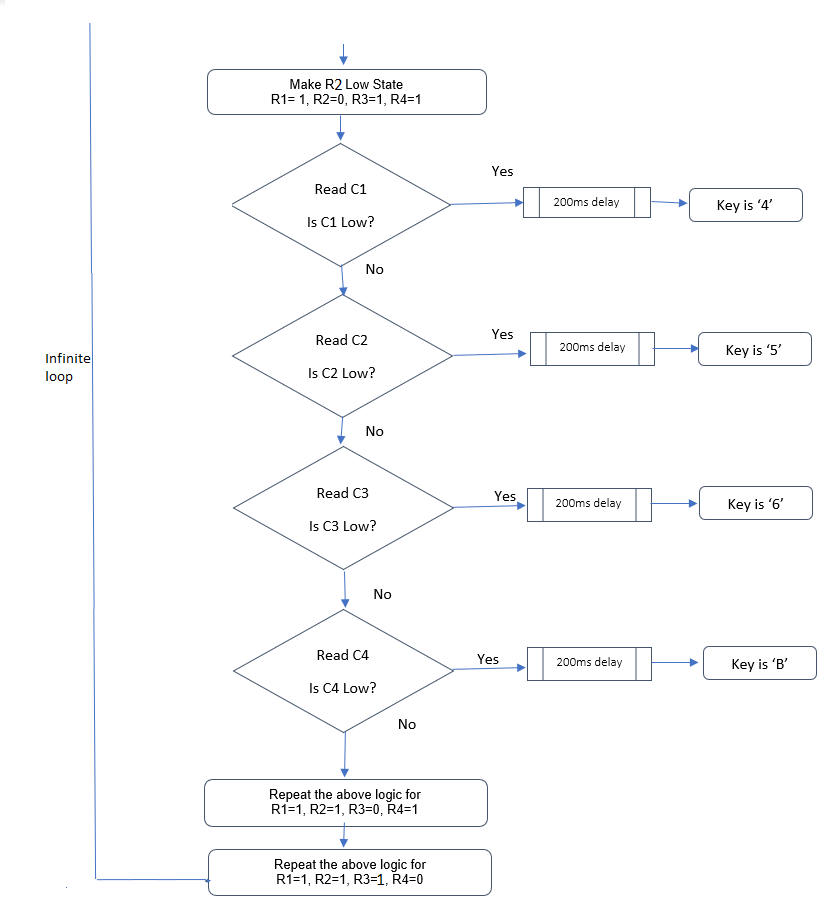
Look at the Flowchart. The first two steps are initialization.
- First, you have to keep all row GPIOs in OUTPUT mode and keep all column GPIOs in INPUT mode.
- After that, make all row GPIOs high state.
- After that, the infinite loop starts. In the infinite loop, first, you have to make R1 Low(0). R2, R3, R4 should be maintained at High(1).
- And after that read C1. Check whether C1 is Low. If it is yes, then you should conclude that the key ‘1′ is pressed. Just use the printf statement to print the letter 1.
- So, in between detecting and printing you give 200 milliseconds of delay or 150 milliseconds of delay. This is for key debouncing. This much amount(200 or 150 milliseconds) is required, otherwise, the software will continuously detect the pressed event and it may execute the printf a couple of times.
- If C1 is not zero, then proceed to the next. Read C2. If C2 is Low, then conclude that the key ‘2’ is pressed. And like that, you have to cover all the columns.
- After that, you have to make R2 low. So, R1=1, R2=0, R3=1, R4=1. And then again you have to scan all the columns, and you have to print the appropriate key.
- And after that, you have to repeat the same logic for R3=0 and repeat the same logic for R4=0. All these things should be in an infinite loop and that’s how you scan the keypad for the key press event.
Button Debouncing
To understand why that delay is required, that is to compensate for the button debouncing.
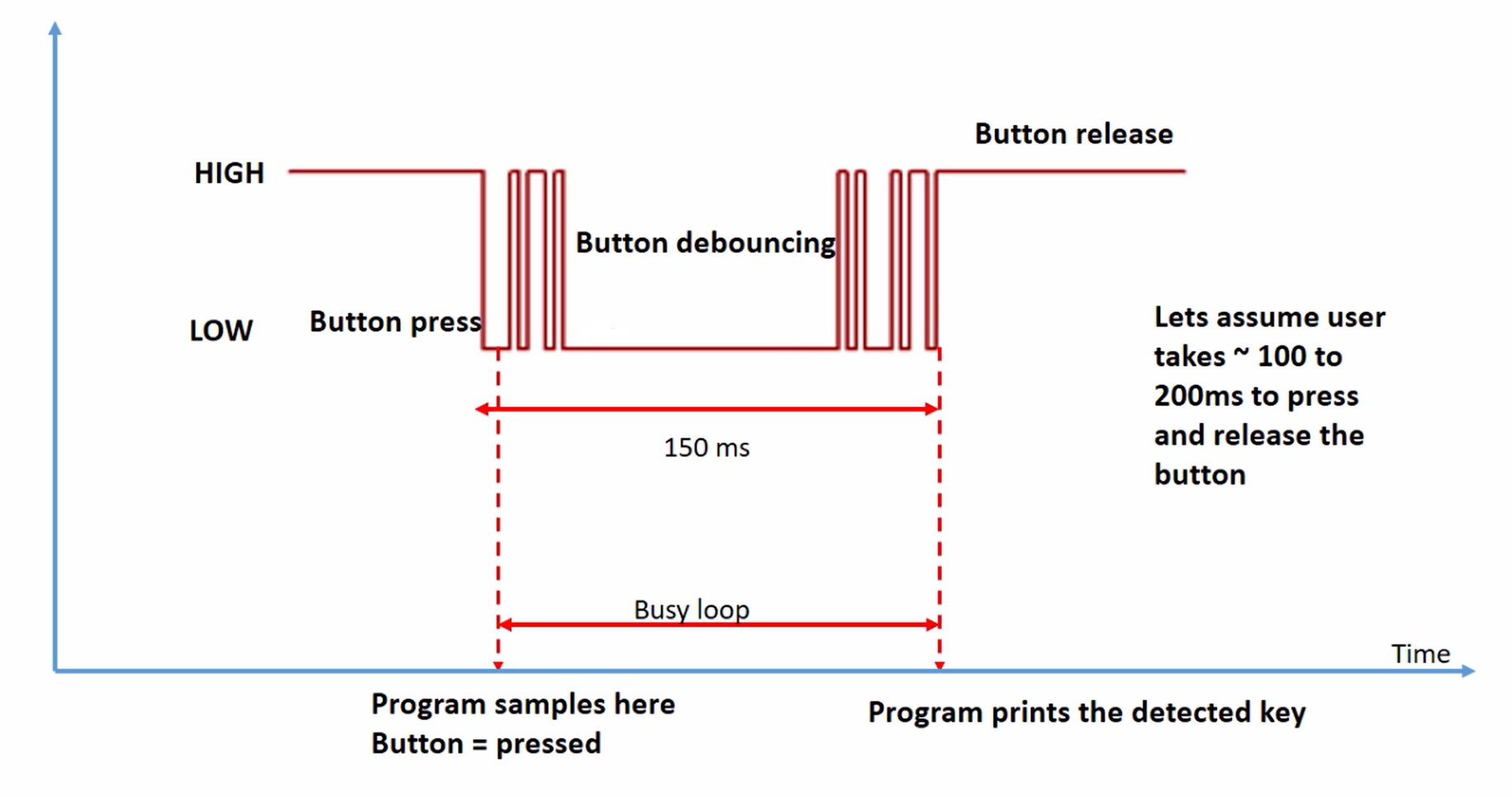
What happens when you press a key?
When you press a key, there will be a metal contact and that metal contact exists for a certain amount of time. Because, when the user presses a key user takes a certain amount of time to release that.
Let’s assume the user takes 100 to 200 milliseconds to press and release the button. So, for that amount of time, there will be a metal contact. There will be a bouncing pattern between high and low. That’s what we call button debouncing.
So, when the user presses a key, the software detects that button is pressed. After that, the software has to wait until it takes the next action. Let’s say 150 milliseconds. For the next 150 milliseconds, the software has to be in a Busy loop. So, Busy loop you can implement by using a for loop.
And once that delay is elapsed the program can take the next action. So, in this case, the program prints the detected key. So, that delay is used to compensate for the button debouncing.
So, either you can implement 200 or 150 milliseconds of delay. Use a for loop to implement this delay. So, a precise delay is not required, you can just approximate.
Some hints:
Step 1:
- Find out the free IOs available on your target board pin headers.
- Decide which are the IO pins you are going to use to handle rows and columns of the keypad.
Step 2: (Initialization phase)
- Create required pointer variables to handle memory-mapped registers.
- Initialize the pointer variables with appropriate memory-mapped register addresses.
- Make use of type qualifiers such as ‘volatile’ if memory-mapped register access is involved.
Step 3:
- Initialization
- Make all row IOs mode as OUTPUT
- Make all column IOs as INPUT
- Activate internal pull-up resistors for all column IOs. This is very important. And for this, you have to refer to the pull-up and pull-down enable register in the reference manual of the microcontroller.
Step 4:
- Implement the key detect logic as per the flowchart.
For the printf, you can use the SWO based printf technique. And I would suggest you to use a bit manipulation technique to code this entire exercise. Don’t use structures and bit fields. So, that is not required. But, I wanted to code this exercise using purely the address manipulation technique using bitwise operators. And later you can always repeat the same exercise using structures and bit fields.
FastBit Embedded Brain Academy Courses
Click here: https://fastbitlab.com/course1

