I2C driver API requirements
In this article, let’s discuss the driver API requirements and user-configurable items for I2C peripherals.

I2C driver APIs:
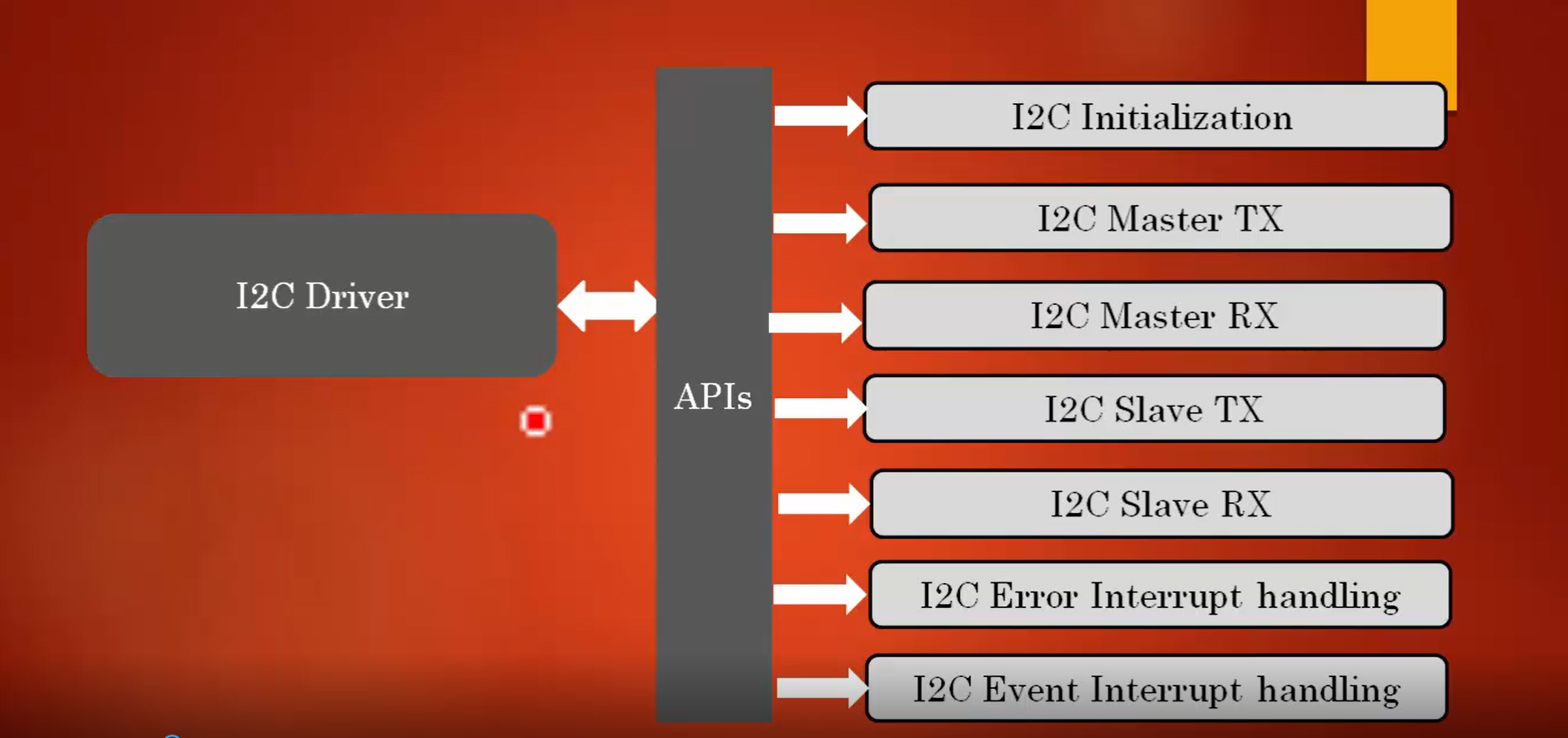
I2C drivers should have I2C initialization APIs and separate APIs for I2C Master TX and I2C Master RX; because the master has to initiate the start condition, address phase, etc.
Since the slave is not going to do all these things, there are separate APIs for I2C Slave TX and I2C Slave RX. There is a separate API for master and slave to transmit and receive data. That’s why I2C Master TX, I2C Master RX, I2C Slave TX, and I2C Slave RX are created as shown in Figure 1.
There are some interrupt handling APIs such as I2C error interrupt handling and I2C event interrupt handling that has to be supported.
Apart from this, you have to keep the peripheral control, the peripheral clock control, peripheral enable/ disable, and lots of other peripheral control APIs.

Configurable items for user application:
The configurable items for the user application are as shown in Figure 2.
- I2C_SCLSpeed: The first configurable item would be user has to mention the SCL speed. Therefore, a Configurational structure with the member element I2C_SCLSpeed is created, where the user can mention SCL speed.
- I2C_DeviceAddress: If the device is acting as a slave, a member element I2C_DeviceAddress is created to store the own address or device address given by the user.
- I2C_ACKControl: In the I2C peripheral, automatic acking is disabled by default. Therefore, the member element or configurable item named I2C_ACKControl is given for the user to decide whether acking should be enabled or disabled.
- I2C_FMDutyCycle: If the communication speed or serial clock speed is more than 100KHz, it is considered a fast mode. In fast mode, the duty cycle of the clock can be varied. A member element called I2C_FMDutyCycle is created to hold the information of varying duty cycles, where the user can mention the value of the duty cycle when the I2C peripheral is in the fast mode.
These four are the configurable items for the user application, and the configuration structure is created by taking the information of all these configurable items.
Exercise

Figure 3 has some exercises that you have to do before start writing the driver.
- Create stm32f407xx_i2c_driver.c and stm32f407xx_i2c_driver.h files in driver’s folder.
- After that, add I2Cx related details such as I2C peripheral register definition structure, I2C base address macros, I2C peripheral definition macros, macros to enable and disable I2C peripheral clocks, and bit position definitions of I2C peripherals to the MCU specific header file.
After finishing the exercise, the driver.c and driver.h files are created in the IDE, as shown in Figure 4.

Add all the I2C related details in the stm32f407xx.h, which is a device-specific header file.
- First, add the base address, as shown in Figure 5.1.

- Add the peripheral register definition structure, as shown in Figure 5.2.

- Add peripheral definition macros, which is as shown in Figure 5.3.

- Add clock enable and disable macros, as shown in Figure 5.4.

- Next is adding bit position definitions of I2C peripheral. For that, create register bit definition macros for I2C_CR1, I2C_CR2, I2C_SR1, I2C_SR2, and I2C_CCR, as shown in Figure 5.5, 5.6, 5.7, 5.8, and 5.9, respectively.


In the following article, let’s see l2C handle and configuration structure.


