Exercise: Understanding MCU clock configuration Part-1
Before implementing any exercise, let’s ask ourselves what exactly the clock speed of our microcontroller is.
Now let’s find out the clock speed of the microcontroller for our project.
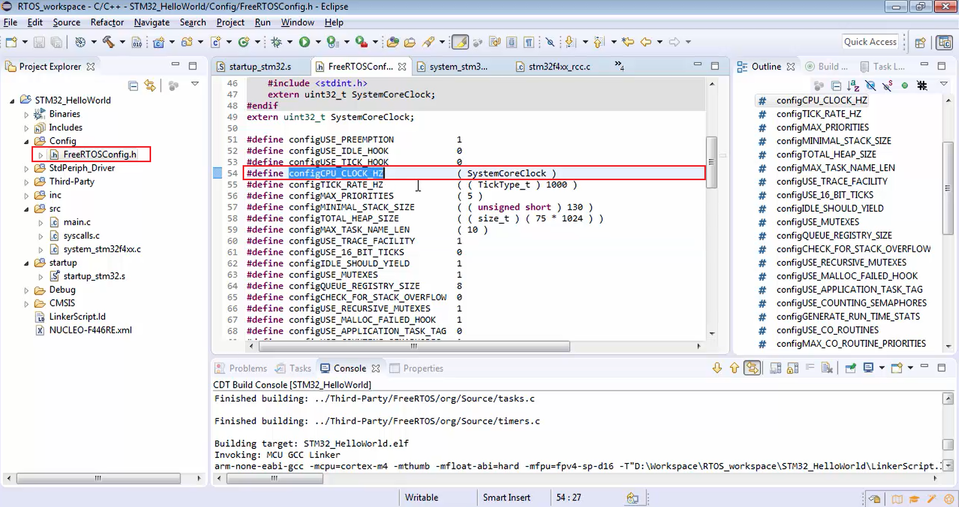
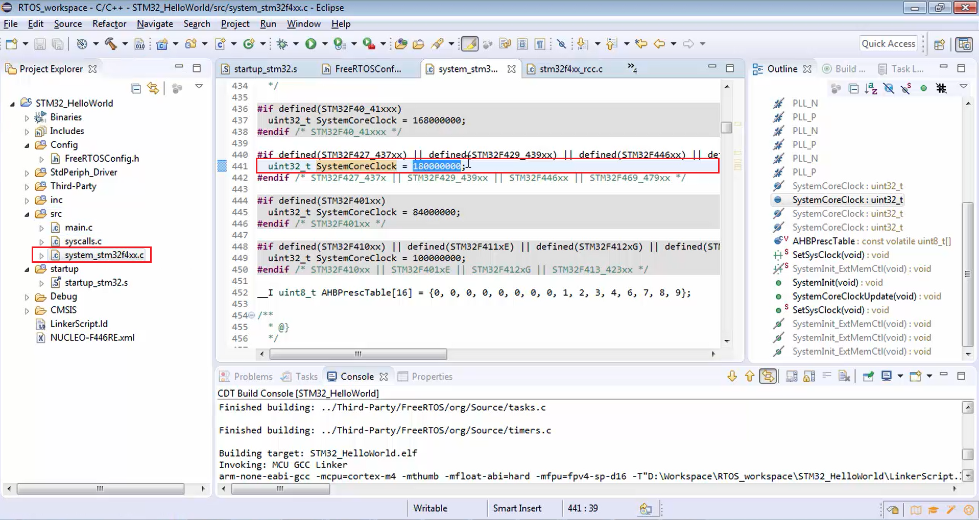
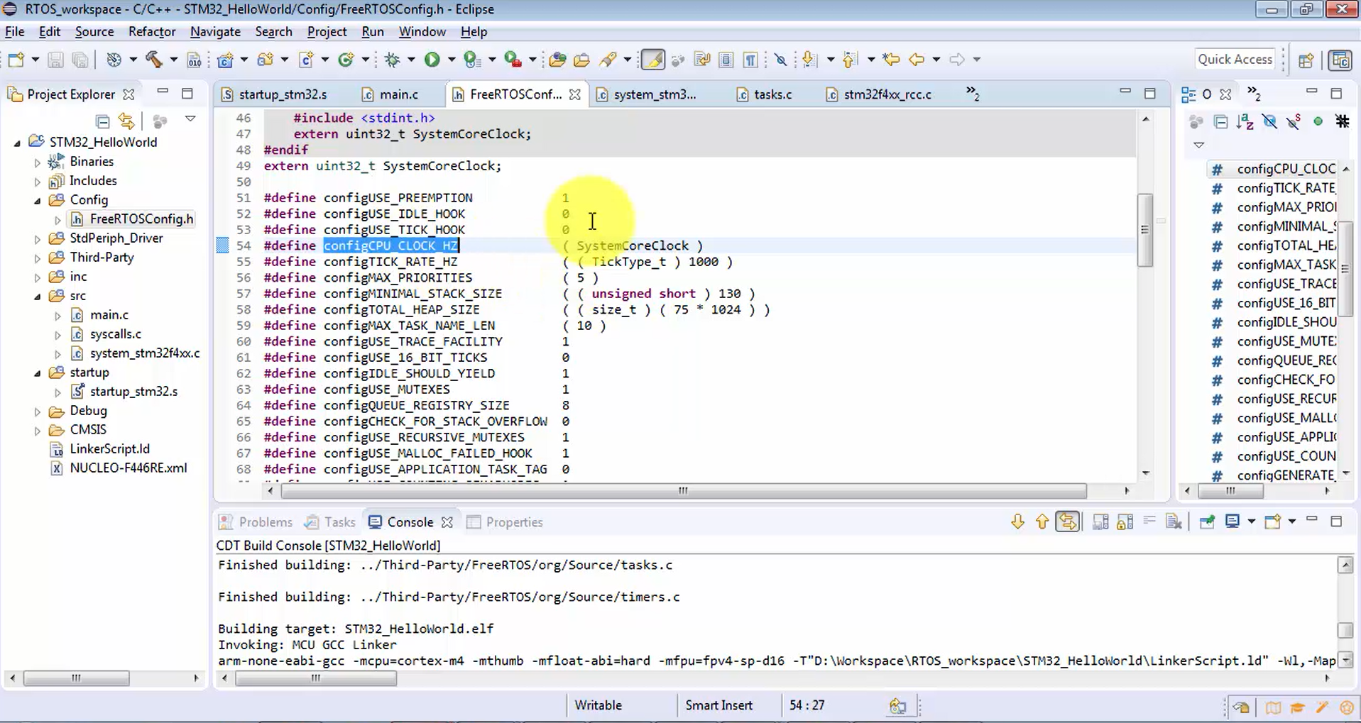
If you go to the FreeRTOSConfig.h of your project, there is one configurable item called configCPU_CLOCK_HZ, which is initialized to the SystemCoreClock variable or symbol.
If you trace the SystemCoreClock variable, it is actually defined in the system_stm32F4x.c file, which is there in the source folder and initialized to 180 MHz, as shown in Figure 2.
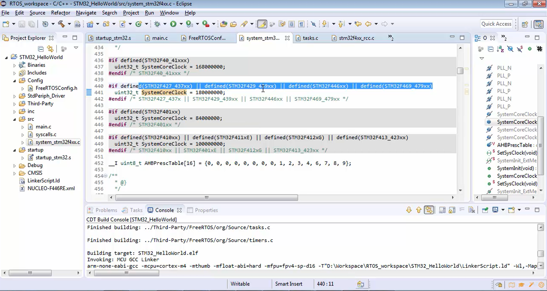
In Figure 3, you can also see that the 180 MHz is applicable to only the microcontroller like STM32F427, STM32F437xx, STM32F439xx, or STM32F446xx.
Now in all these microcontrollers, the system clock, i.e., the microcontroller’s main clock, can rise up to 180 MHz but remember, that is not the default case. It can go up to 180 MHz maximum.
Let’s say you are using the STM32lx series of the microcontroller; then you may not be able to go up to 180 MHz. You may end up having a maximum of 80 MHz.
Remember that this discussion is not just bound to STmicroelectronics microcontrollers. This concept is applicable to any microcontroller, whether it is from NXP, TI, or Atmel. Everywhere the microcontroller needs a clock. That clock is called a system clock.
For the system clock, there will always be a default case as well as the maximum capacity. By going through the reference manual of the microcontroller, you can understand the default clock and the maximum value of the system clock of the microcontroller. There is no other way to get this information. You have to obtain it from the reference manual.
Now let’s go to the reference manual to understand this.
In the reference manual of the STM32F446RE microcontroller, go to the reset and clock control or RCC, as shown in Figure 4.
RCC is the block that is used to control the clock to the various parts of the microcontroller like the processor, peripherals that are hanging on the AHB domain, peripherals that are hanging on the APB domain, and to the various other sections of the microcontroller like memories, etc. Basically, this block manages the clock.
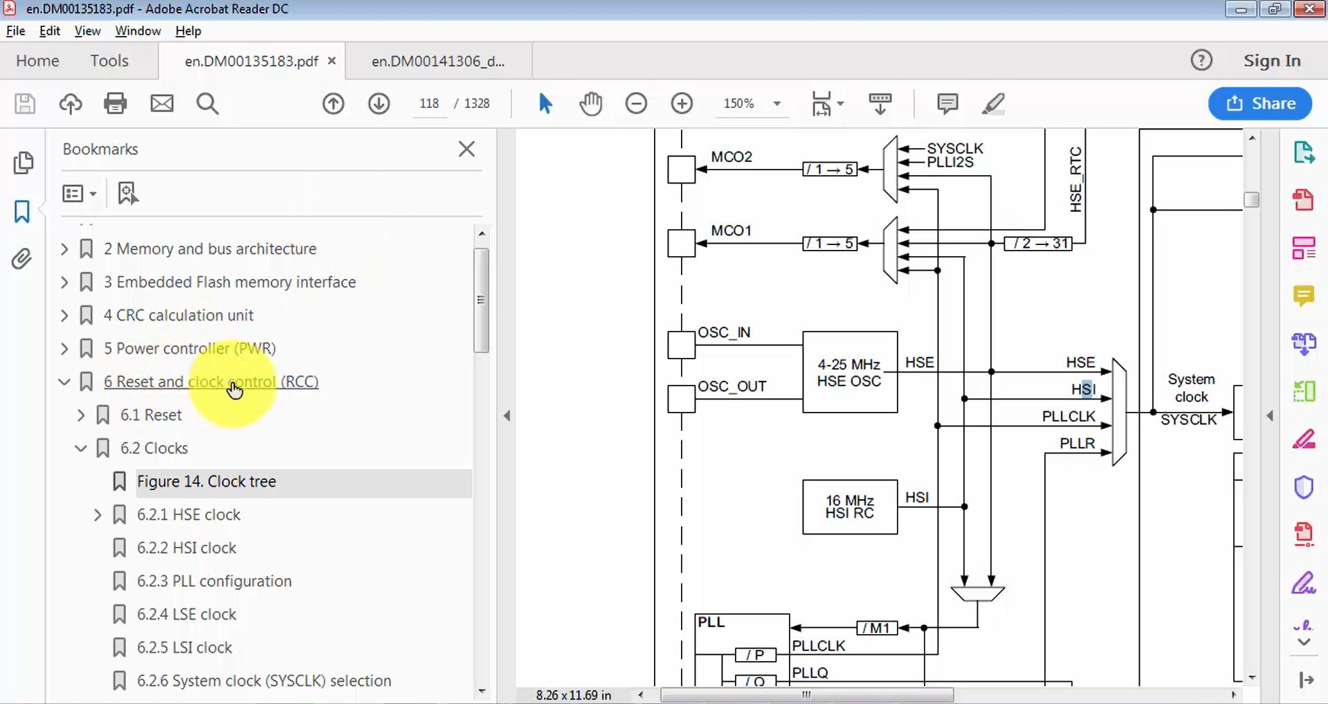
In the RCC section, you will find a clock tree (Figure 5), just open that, and in the clock tree, you will find a CPU clock, which is getting generated by this engine. If you trace this CPU clock, it will actually be going to the CPU of the microcontroller, i.e., ARM processor.
The CPU clock is derived from the system clock, and the system clock is derived from a couple of sources that are HSE, HSI, PLLCLK, and PLLR. HSE stands for High-Speed External, which is the crystal that you connect to the microcontroller externally.
Remember that, by default, the microcontroller doesn’t come with the crystal. The crystal is something that you provide externally to the microcontroller on the PCB.
In most of the products, the crystal may not be present. That’s why the microcontroller should not drive the system clock from HSE by default because HSE may not be present. That’s why there is another source called HSI or High-Speed Internal, which is internal to the microcontroller and is derived from the RC oscillator, which is there inside the microcontroller.
You can observe HSI RC in Figure 5, and its value is 16 MHz in this microcontroller, which may not be true for some ST family microcontrollers. Some microcontrollers may have HSI as 8 MHz. So, the internal RC oscillator is considered as HSI, and it provides a clock of 16 MHz.
In Figure 5, you can see that the HSI RC comes all the way to the HSI. Since it is internal to the microcontroller, it is used as a default system clock. This is the reason the system clock will be 16 MHz by default.
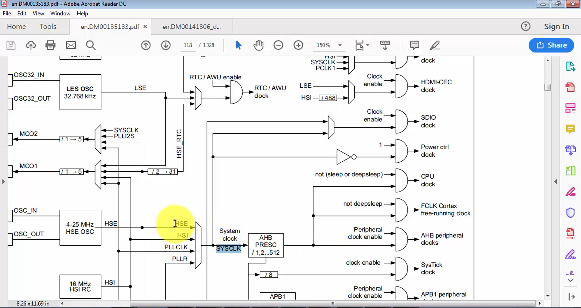
The microcontroller will also have a clock generating engine called PLL, and by using that PLL, you can produce high-speed clocks.
By taking the help of PLL, you can reach up to 180 MHz in this microcontroller. PLLCLK helps you to achieve higher and higher clock speeds, and the maximum value is 180 MHz. But remember that by default, HSE will be off PLL’s will be off. The main PLL block of the microcontroller will be off by default.
So, the system clock will always derive the clock from HSI. That’s why 16 MHz will be delivered to the CPU. If the AHB prescaler is 1, then the system clock is directly fed into the CPU clock. 16 MHz is the default clock.
Now let’s go to the FreeRTOSConfig.h file of your project (Figure 6).
In that hex file, there is one configurable item called configCPU_CLOCK_HZ. You have to configure this configurable item with the clock frequency you deliver to the CPU clock, which is then equated to SystemCoreClock.
In Figure 2, the SystemCoreClock is mentioned as 180 MHz, which is a maximum value. That means that this project somehow turns on the PLL. Because without PLL, you can’t go up to 180 MHz. That means somewhere, this project is doing PLL configuration to boost the clock to 180 MHz. So, you have to find out the initialization code that configures the PLL because we have not done any PLL configuration.
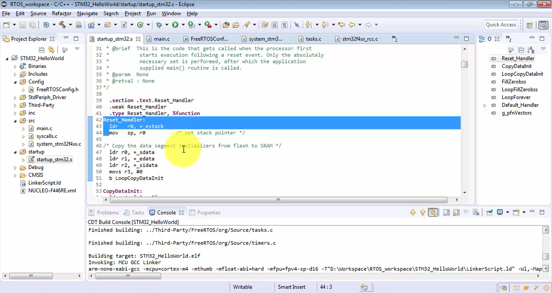
Now let’s find out that initialization code. Let’s trace all the way from the reset handler. Because whenever you reset the microcontroller, the first handler (or function) that runs is the reset handler.
Now, let’s go to the start-up code shown in Figure 7, and here you can find a reset handler written in assembly. The reset handler begins from line 42.
FastBit Embedded Brain Academy Courses
click here: https://fastbitlab.com/course1