Exercise: USART send data to Arduino
Now let’s test the USART_SendData API with one exercise.
Exercise:
Write a program to send some data or some message over UART from STM32 board to Arduino board. The Arduino board will display the message that is sent from the ST board on its serial monitor. Consider the baud rate as 115200bps, and the frame format would be 1 stop bit, 8 bits of user data, and no parity.
Solution:
Setting up the STM32 Application:
- Create an application file (e.g., 015uart_tx.c) for sending data via UART.
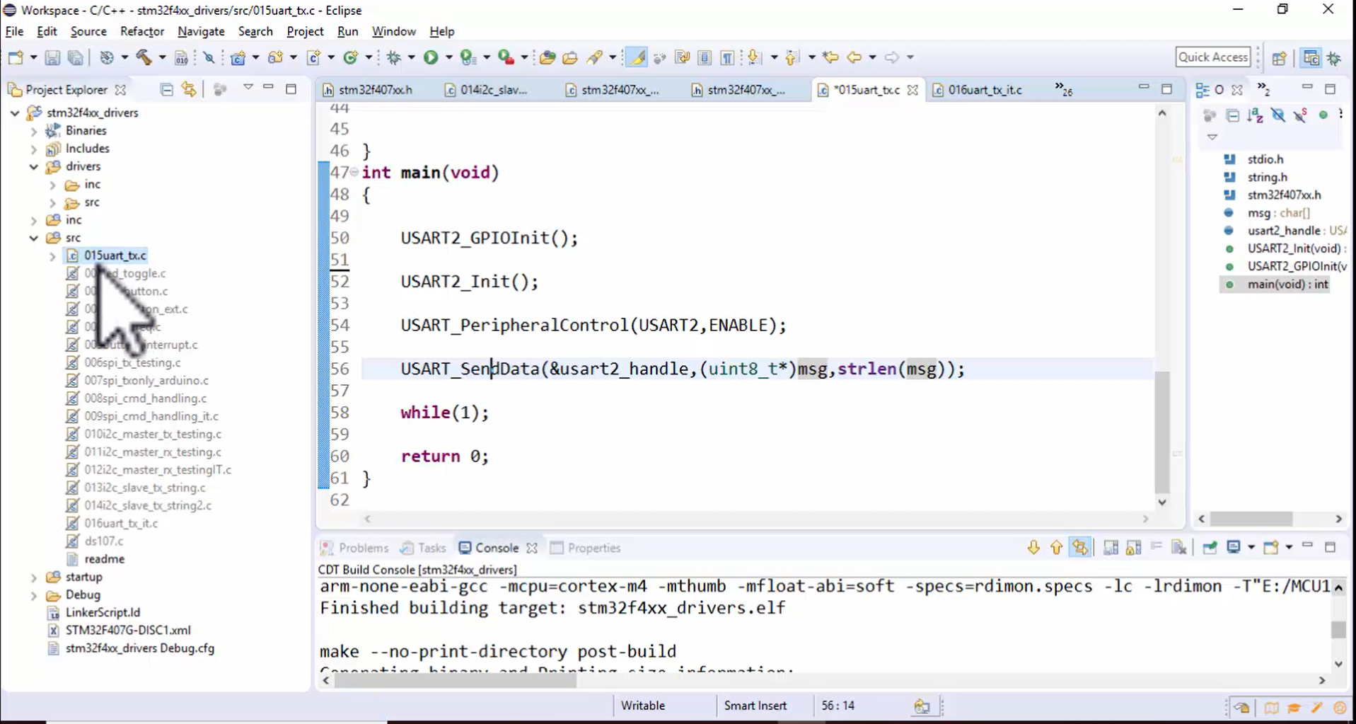
1. The application with the name 015uart_tx.c is already created, as shown in Figure 1.
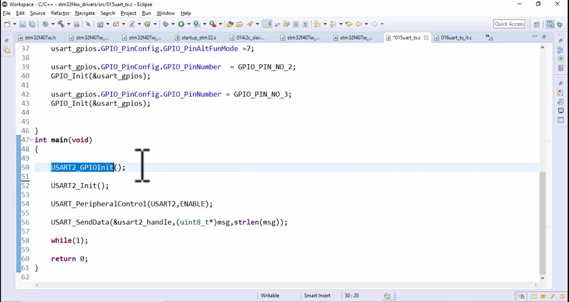
2.Initialize GPIO pins for USART.
First, you have to do the GPIO_Init for the USART peripheral. For this application, you can use any USART peripheral you want. Let’s use USART2 (Figure 2).
3. Configure the pins for USART2 TX and RX based on the alternate function mapping table.
Configure the pins for the USART2 peripheral: You should use 2 pins that are TX and RX, which you can get from the alternate functionality table (Figure 3) of the datasheet.
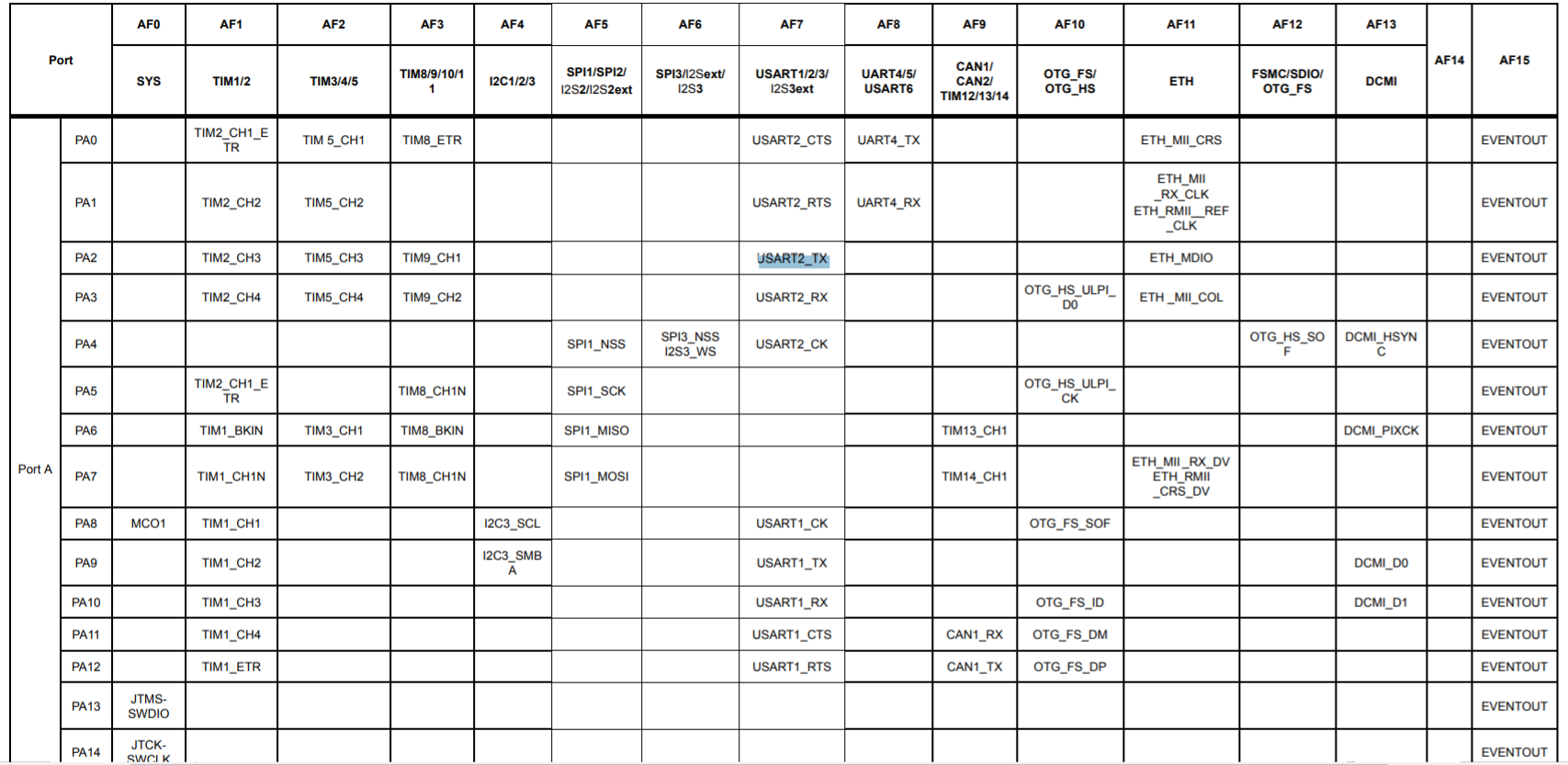
You can see in the alternate function mapping table of our microcontroller, PA2 can be used as USART2_TX, and the alternate function mode should be 7.
PA3 can be used as USART2_RX, and you should keep the alternate functionality mode AF7. You can use any of the pins. It need not be PA2 and PA3. But select the pins according to your board and according to the availability of those pins on the header of your board.
Hardware Connections:
4. After the selection of pins, you have to make the connection with the Arduino board.
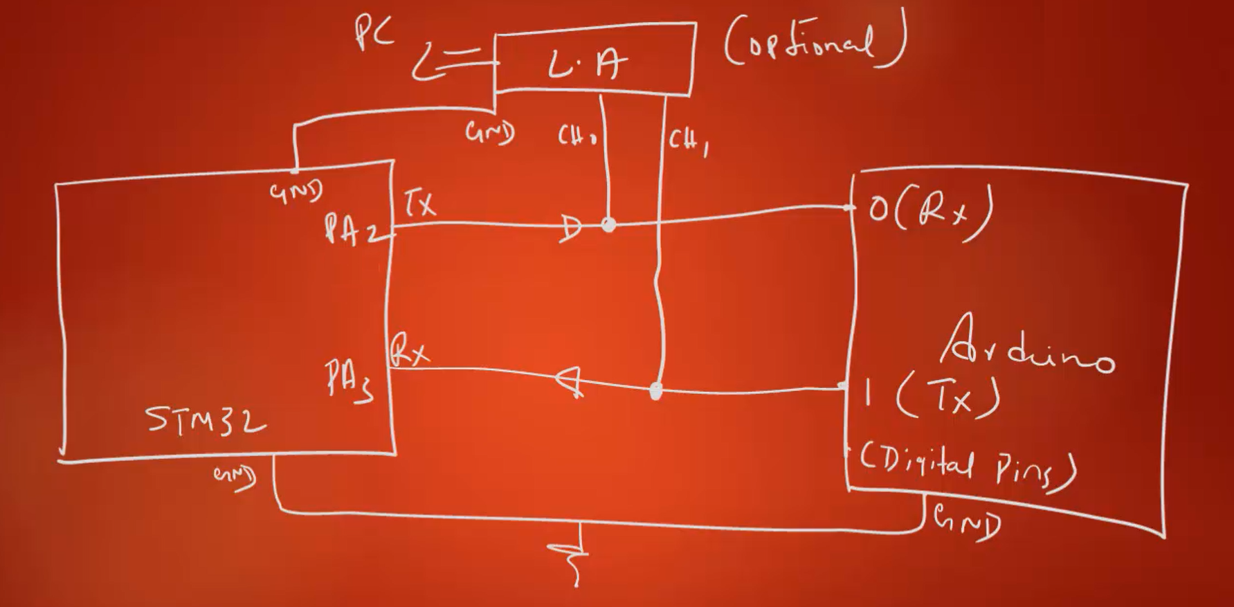
- Connect the TX pin of STM32 (PA2) to the RX pin of the Arduino board.
- Connect the RX pin of STM32 (PA3) to the TX pin of the Arduino board.
- Connect the ground points of both boards together.
In Figure 4, you can see that the PA2, i.e., TX, must be connected to the RX pin of the Arduino board.
The UART_RX pin on the Arduino board is digital pin number 0. So, connect TX to the RX pin of the Arduino board. Then connect PA3, i.e., RX of STM32 board, to the TX pin of the Arduino board. On Arduino, the TX pin will be digital pin number 1. After that, connect the ground points of both the boards to a common ground.
If you have a logic analyzer, then you can use it. Make sure that you connect the ground to the ground point and channel 0 of the logic analyzer to TX pin and channel 1 to the RX pin. The logic analyzer is optional; use only if you have it.
Arduino Sketch:
5. Download and upload the “001UARTRxString.ino” sketch to the Arduino board.
6. Implementing USART2 Initialization:
- Initialize GPIO pins for USART2 using
USART2_GPIOInit().
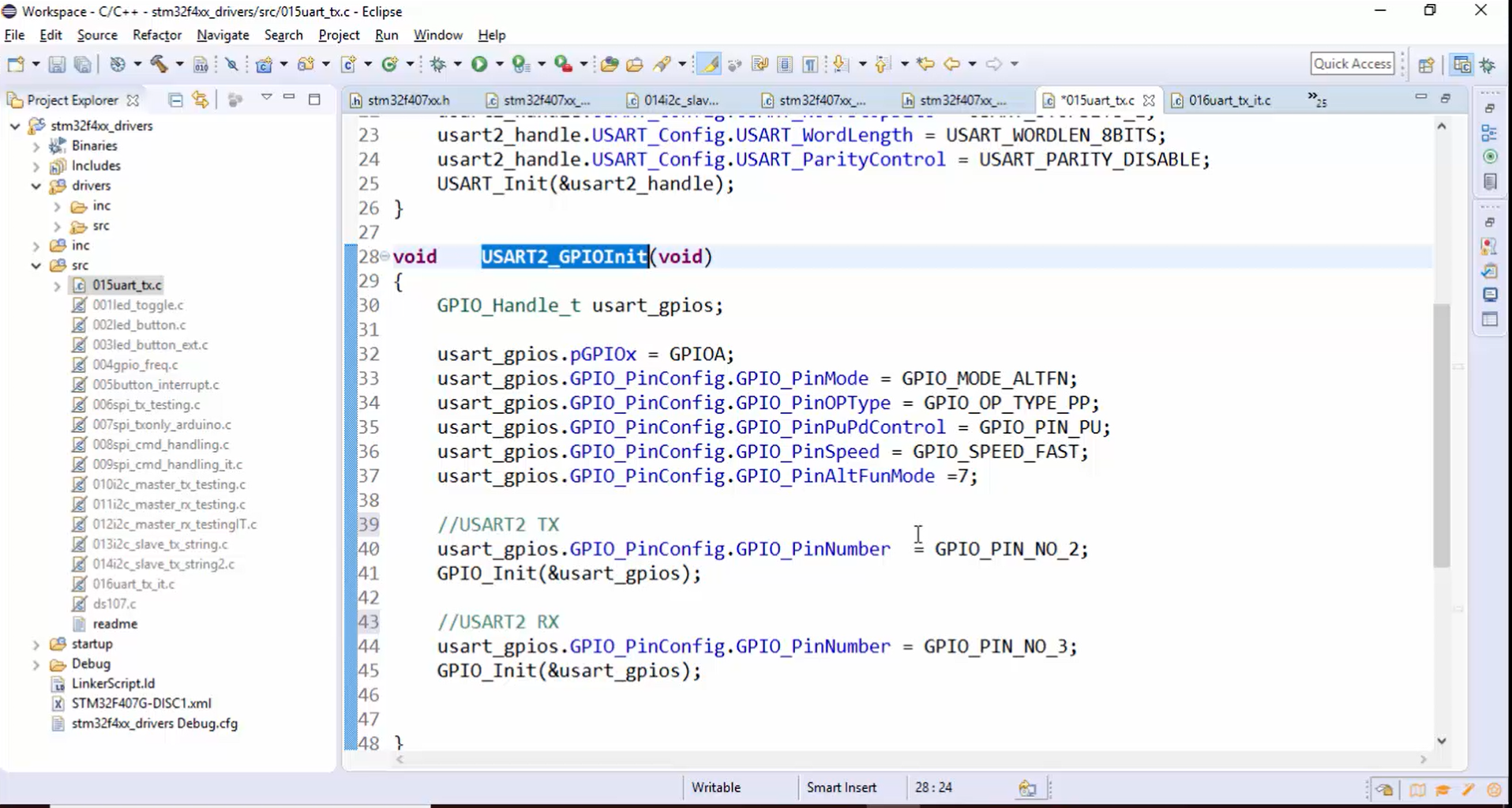
Implement the USART2_GPIOInit() (Figure 5): Initialize GPIOA pin number 2 and GPIOA pin number 3 for the alternate functionality mode 7, as shown in Figure 5.
Here the pin mode will be an alternate function, output type you can use push-pull, need not to use the open drain. You can use an internal pull-up resistor (GPIO_PIN_PU). That means you can activate the internal pull-up resistor.
After that, the speed can be anything. So, you can keep either speed fast, medium, it doesn’t matter.
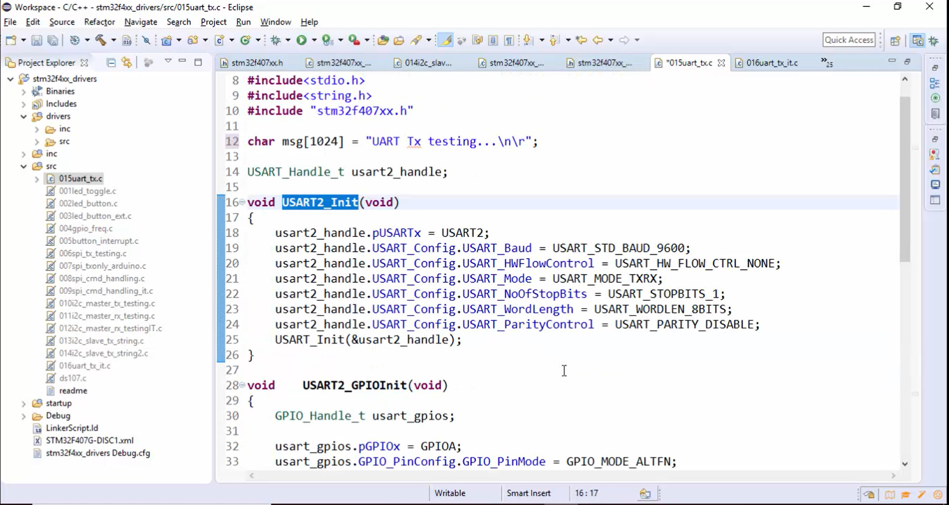
7. Initialize USART2 using USART2_Init() with appropriate configurations:
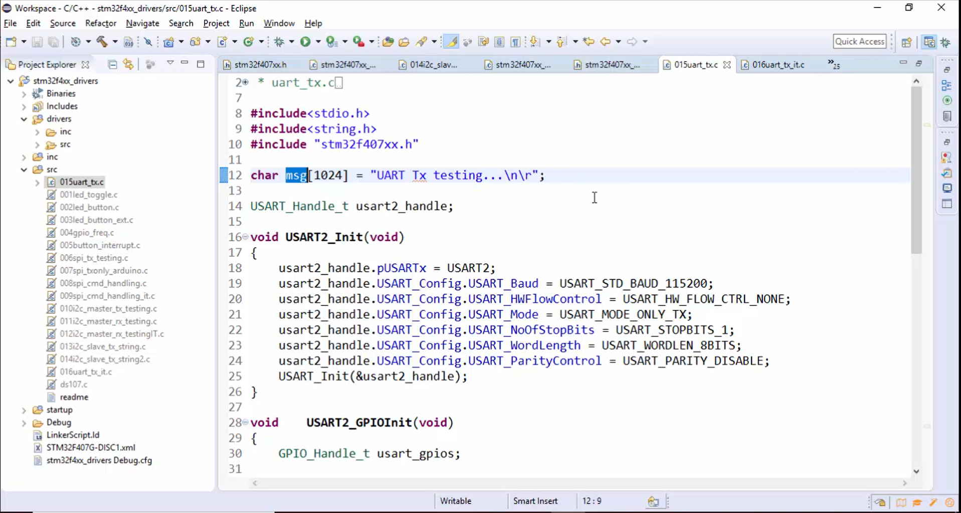
In this section, the handle variables are initialized as follows:
- Mention the base address of the USART peripheral that you want to use in the application.
- After that, mention the baud rate. For this application, let’s use the baud rate of 115200bps.
- Hardware control is not required for this application.
- Initialize the USART_Mode to USART_MODE_ONLY_TX since you are Txing the data, not RXing.
- Number of stop bits will be 1.
- The word length will be 8 bits of user data.
- The parity will be disabled since you are not going to use any parity here.
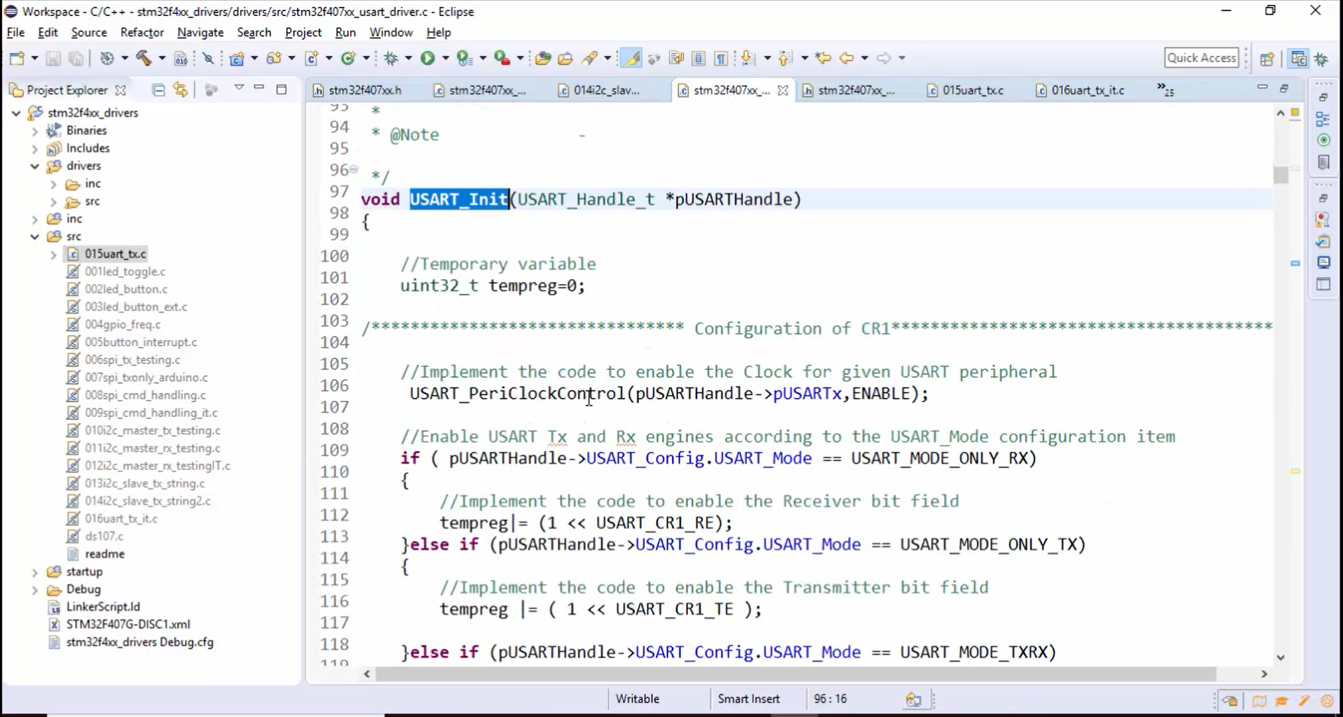
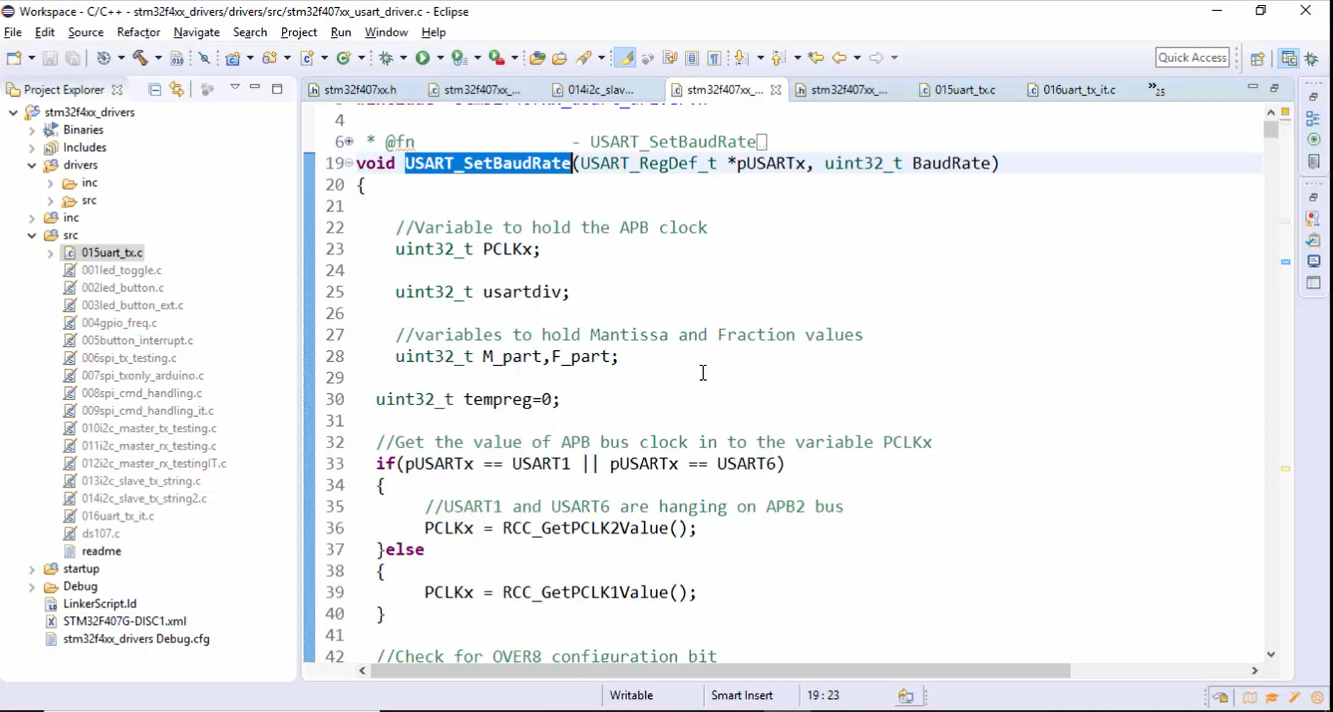
- Call the USART_Init() API. Remember that in the USART_Init, everything should be completed, as shown in Figure 7. Otherwise, the application will not work properly. Therefore, resolve all the TODOs and complete the USART_Init() API, and at the end, there must be USART_SetBaudRate() function, where the baud rate is configured. If you are not yet placed this code, then please complete this USART_SetBaudRate(), as shown in Figure 8.
8. Activate the USART peripheral:
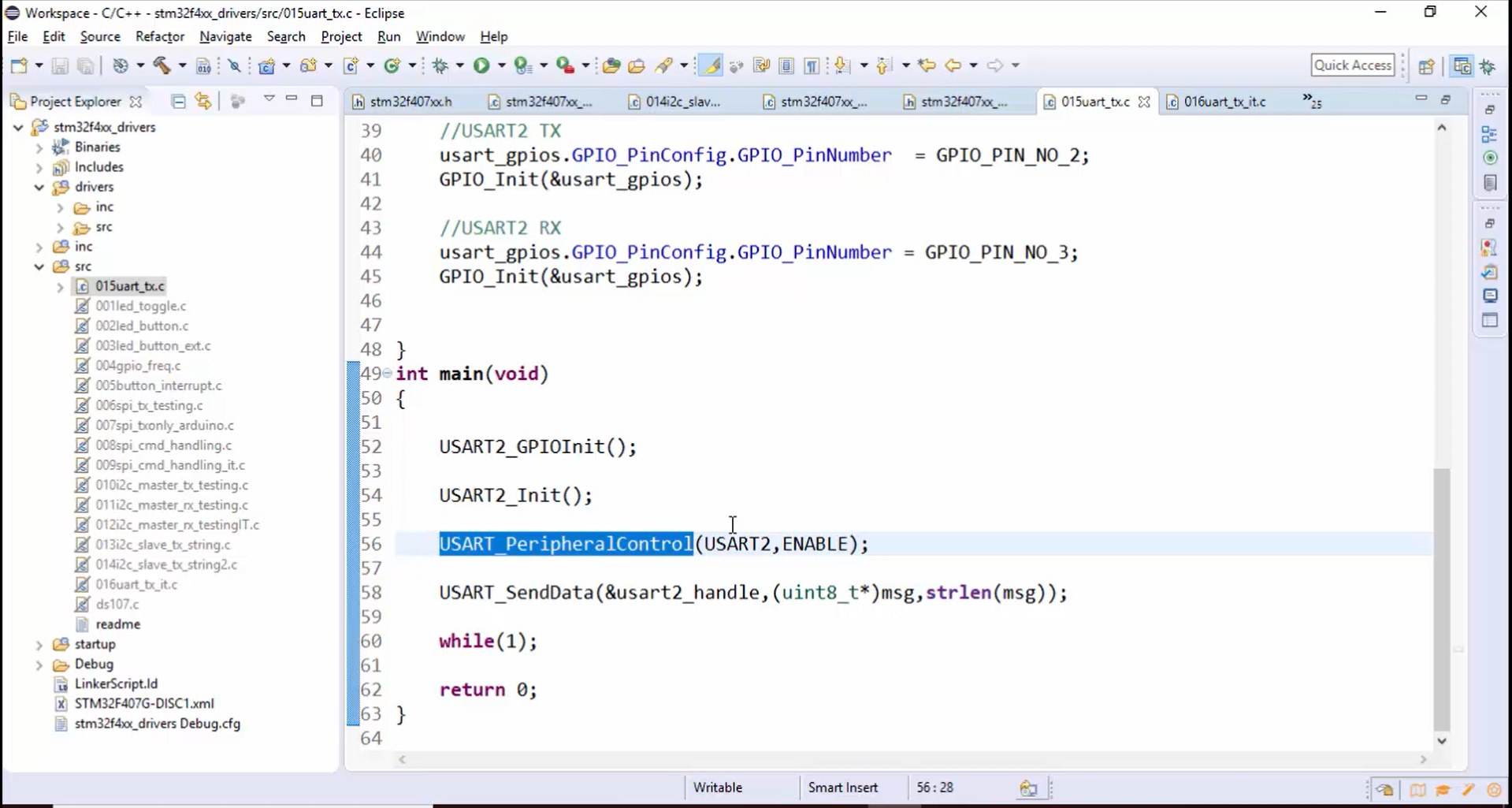
You have to enable the USART peripheral in the main function, as shown in Figure 9.
9.Sending Data:
- Use
USART_SendData()to send a message from the STM32 board to the Arduino board.
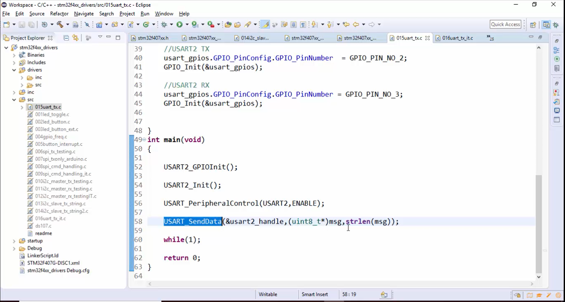
For USART_SendData(), you have to give the parameter, as shown in Figure 10, and the message will be a small message which is there in the global space UART Tx Testing (Figure 11).
10. Now let’s test this application.
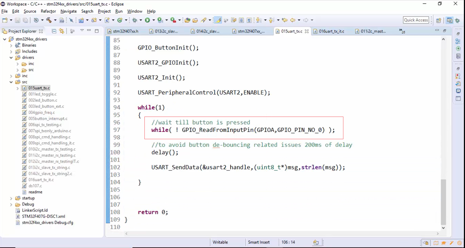
First, place the button code after peripheral control, as shown in Figure 12, so as to trigger the transmission only when the button is pressed. This code will wait till the button is pressed and then send the data. So, let’s keep everything in the while loop and remove the while loop at the end.
11. Compile the project (Figure 13).
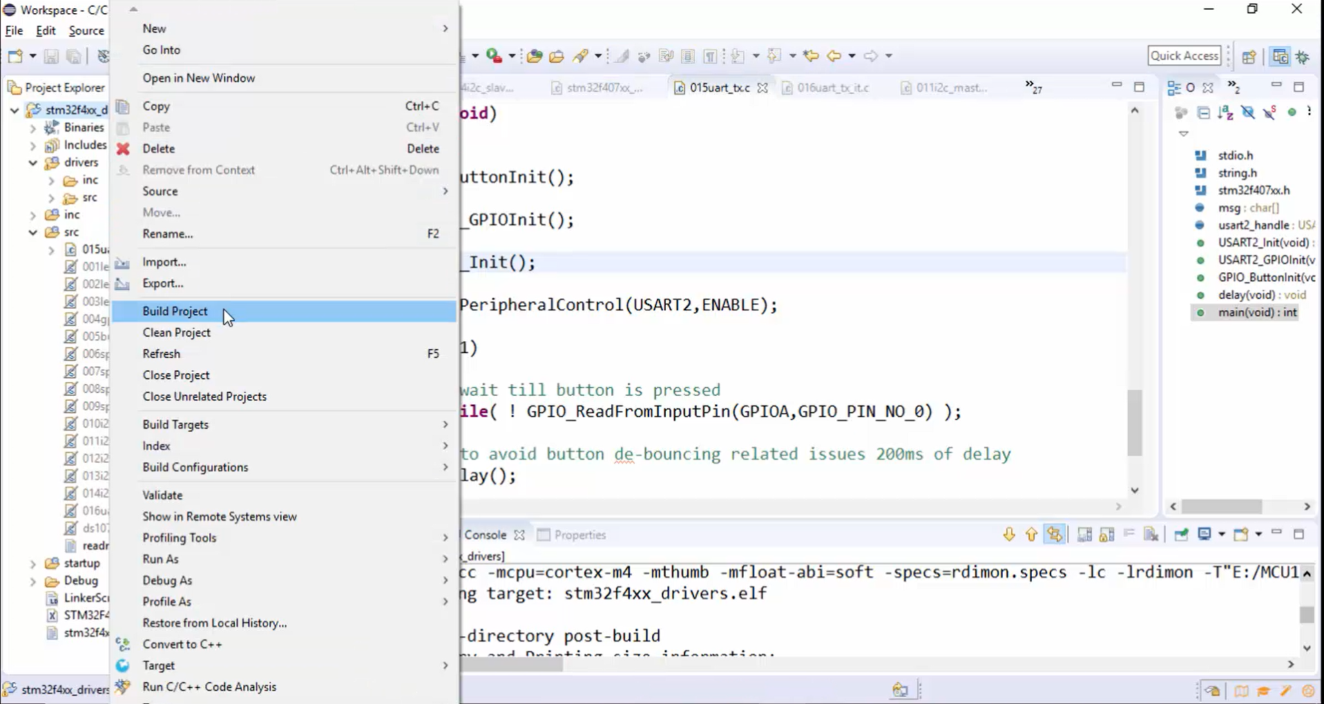
12. The project is compiled successfully. Now let’s download the code into the board.
13. After that, make all the required connections between the Arduino board and the ST board. Connect TX pin to the RX pin of the Arduino board, and make other connections.
Once you complete the connections, go to the sketch and just compile the sketch (Figure 14) because you need to download this sketch into the Arduino board.
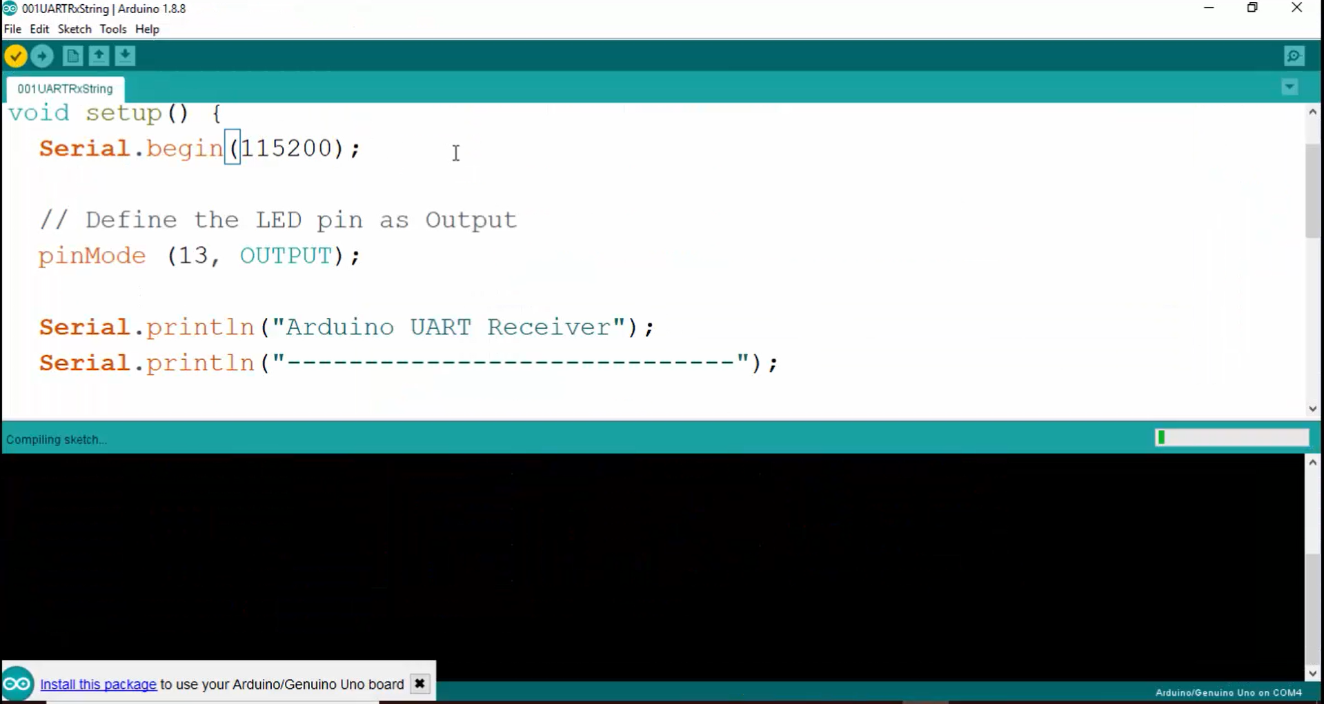
14. Download the sketch into the Arduino board (Figure 15).
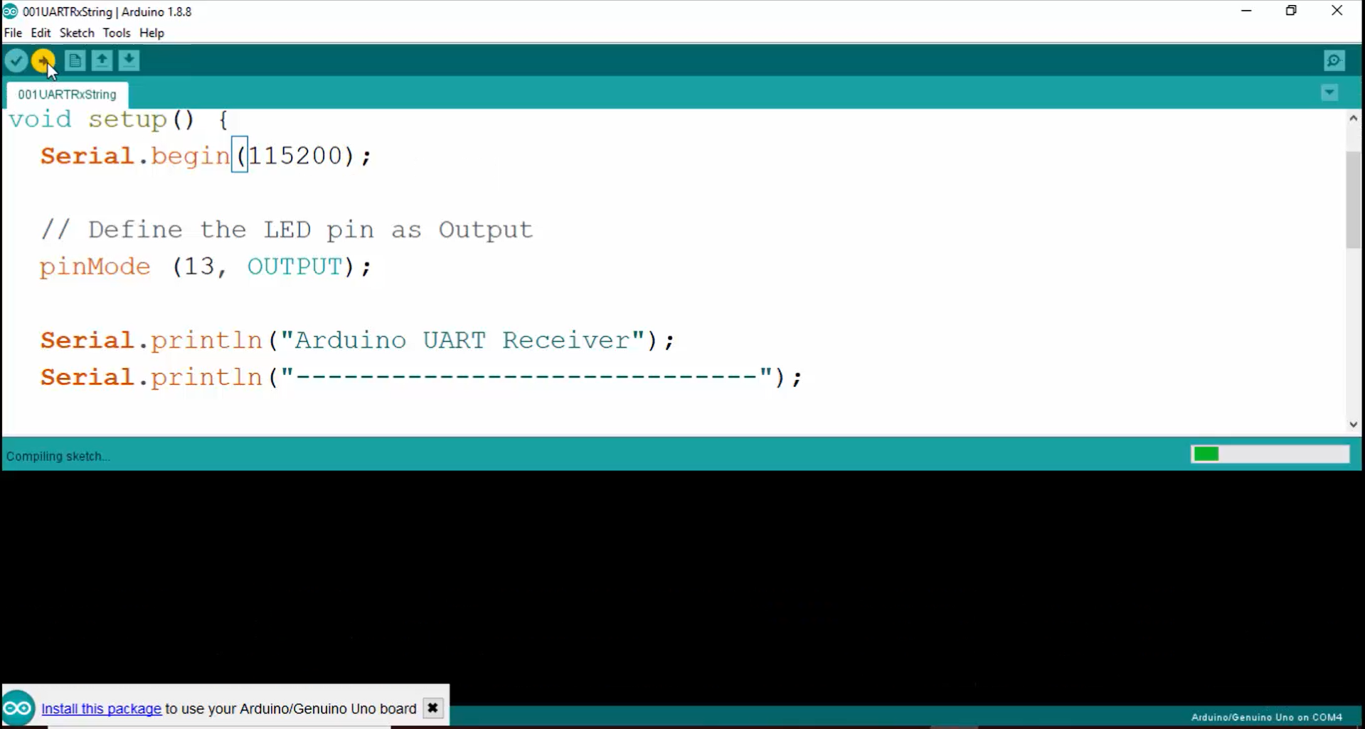
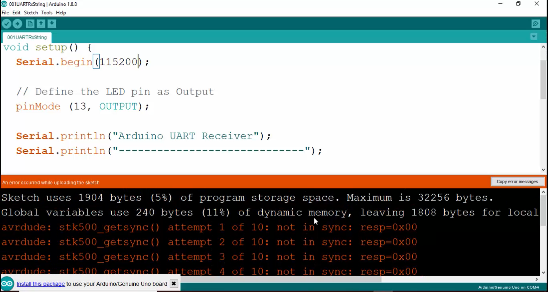
15. While uploading, you may face some issues, as shown in Figure 16.
These errors arise since the Arduino software is not able to communicate with the Arduino board. That’s because the RX pin of the Arduino board is already held by ST connections. That’s why now remove the connections that you have made to the RX pin (Figure 17) of the Arduino board and retry to upload.
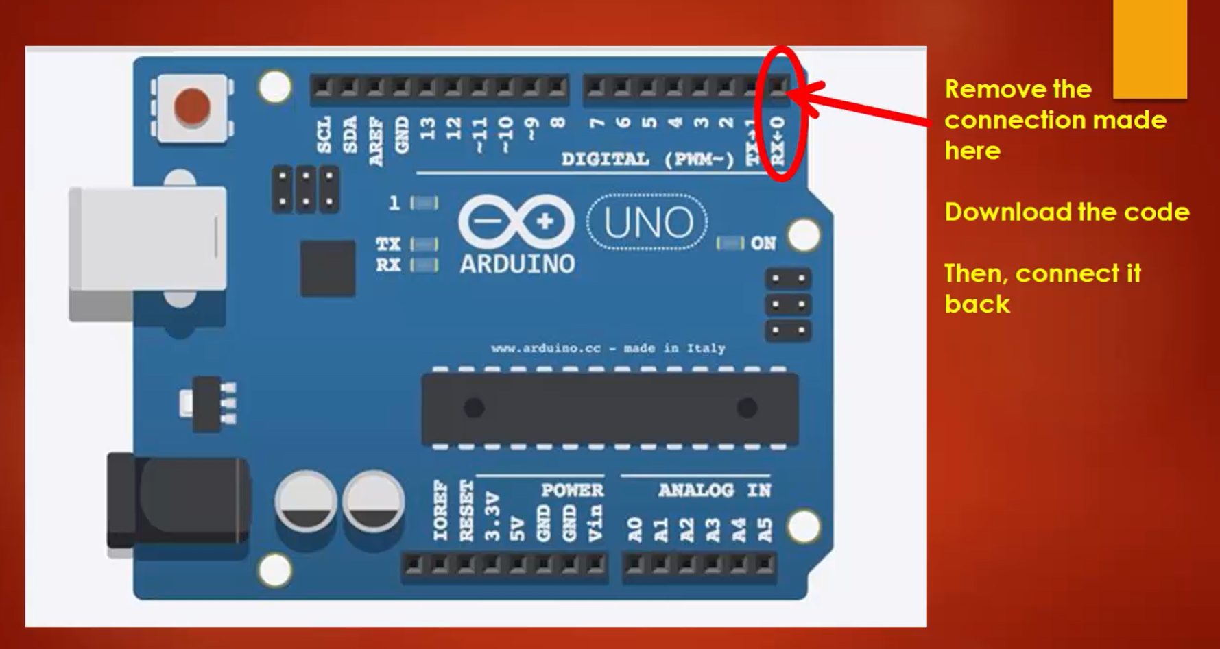
16. Again, try to upload the code into the Arduino board. Now from Figure 18, you can see that the download is successful.
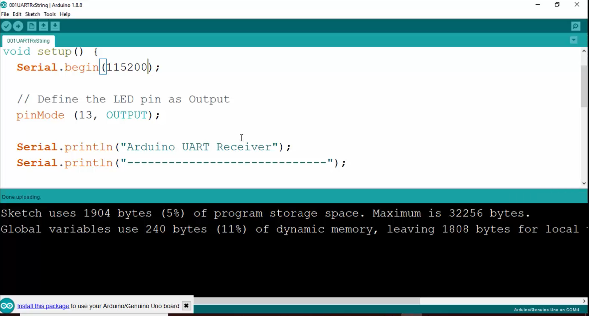
17. Do the connection to RX (digital pin number 0) that you removed previously.
18. Go to tools and open the serial monitor (Figure 19).
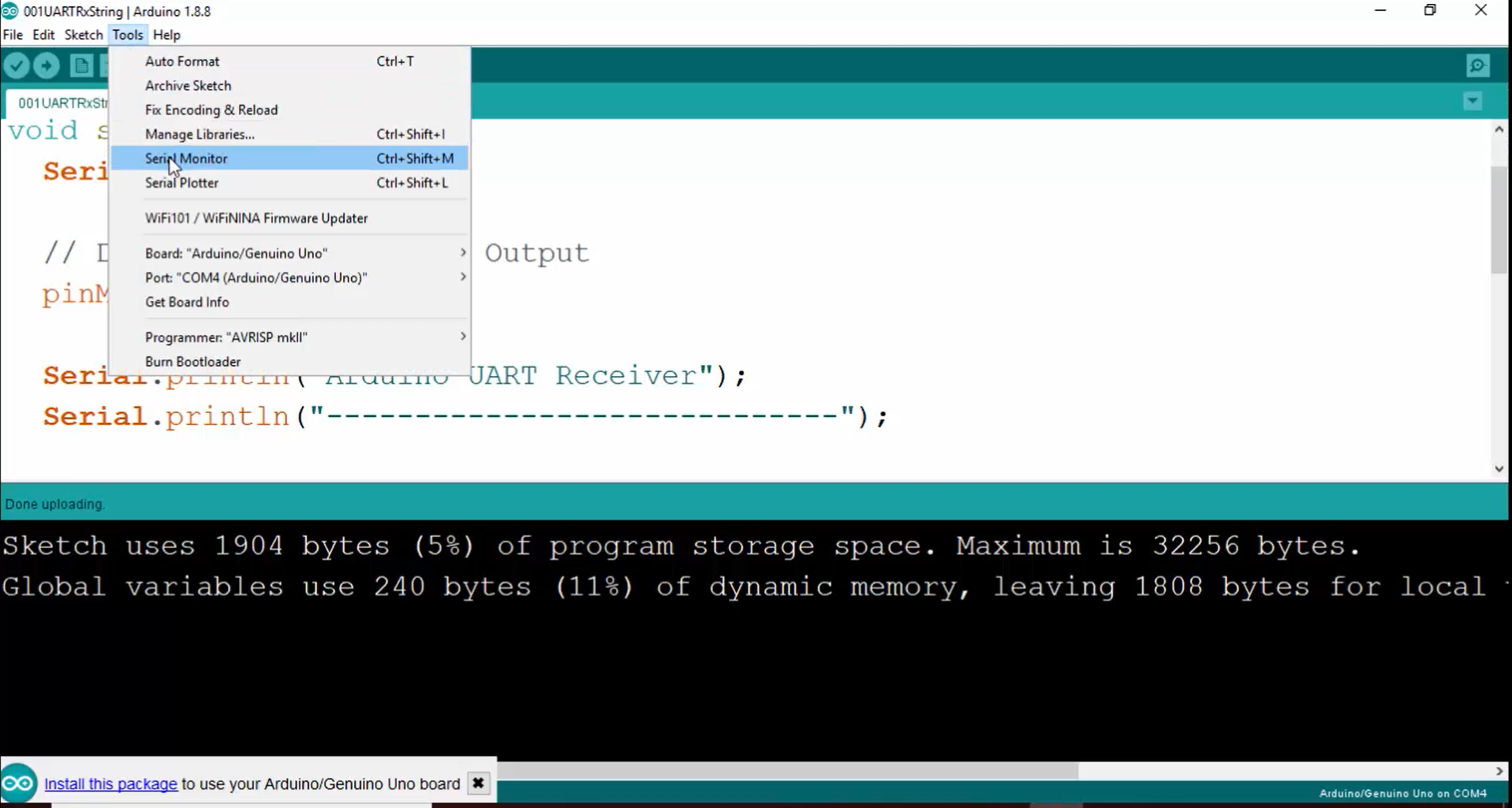
19. The serial monitor must print the message written inside the print statement, but it is printing some garbage values (Figure 20).
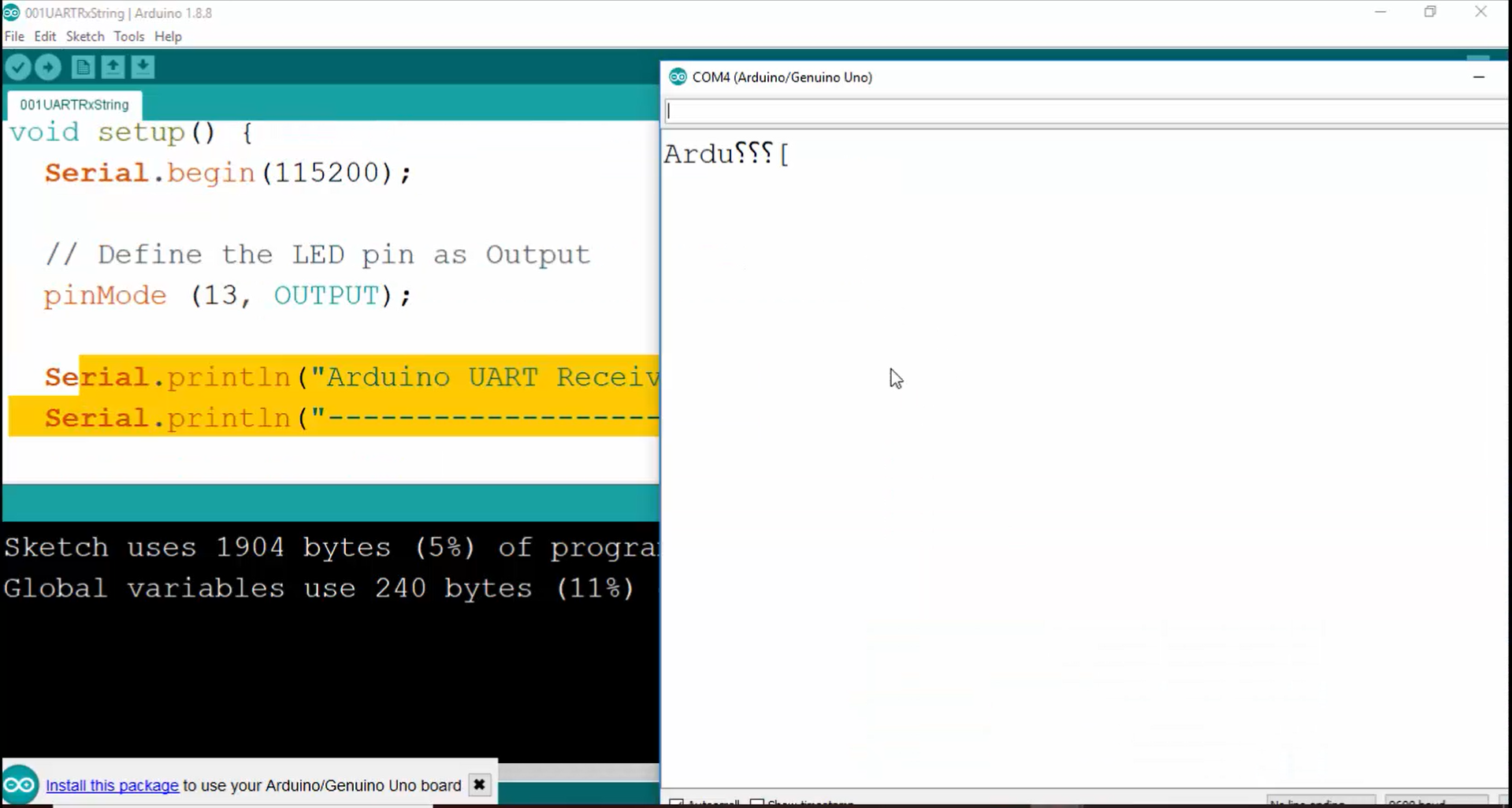
20.Ensure that the baud rate is consistent between the two boards (115200 bps in this case).
Now change the baud rate to 115200 (Figure 21).
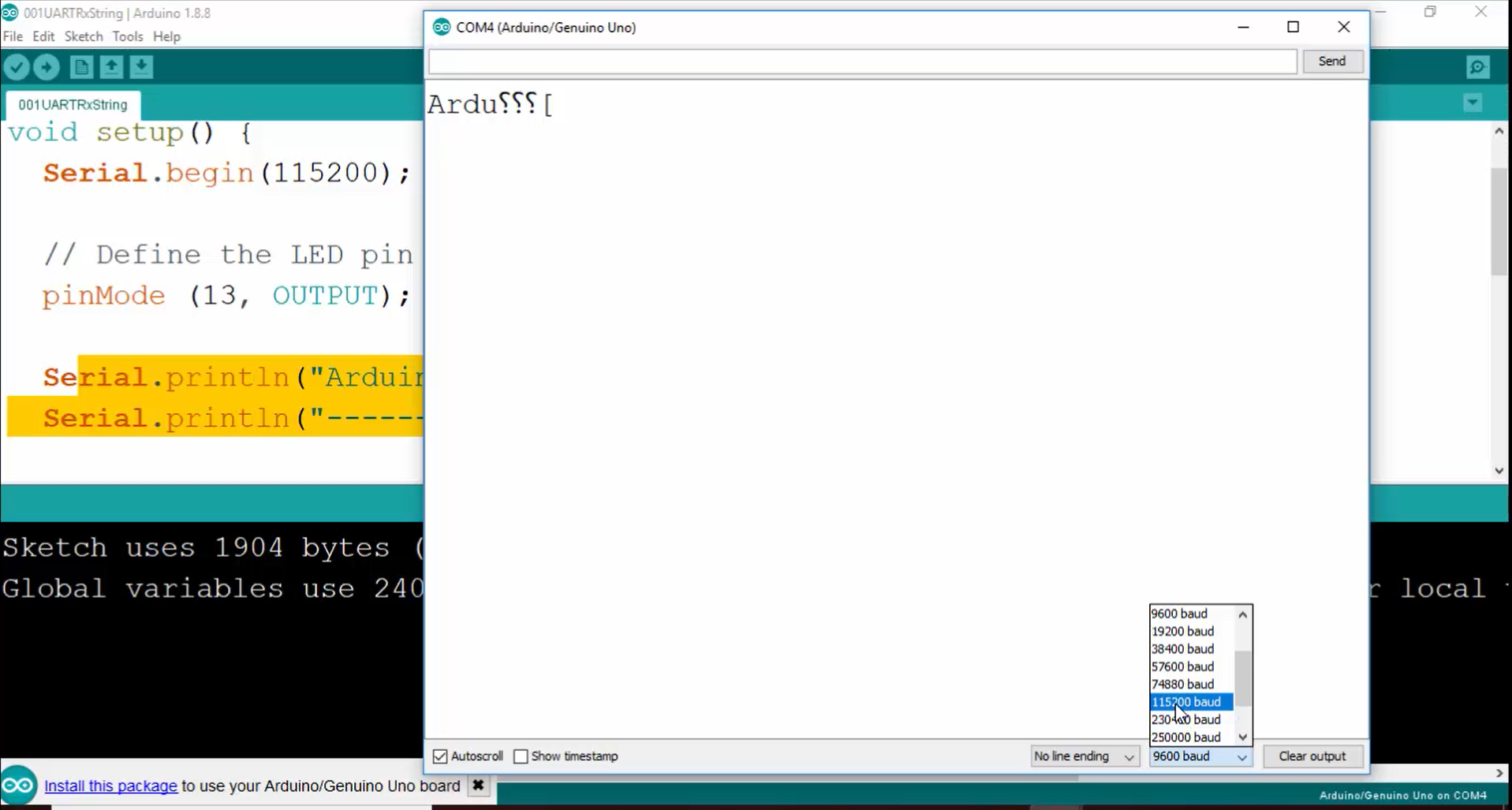
21. After that, press the user button on the ST board. Now on the serial monitor, you can see that the Arduino sketch is receiving the string properly (Figure 22).
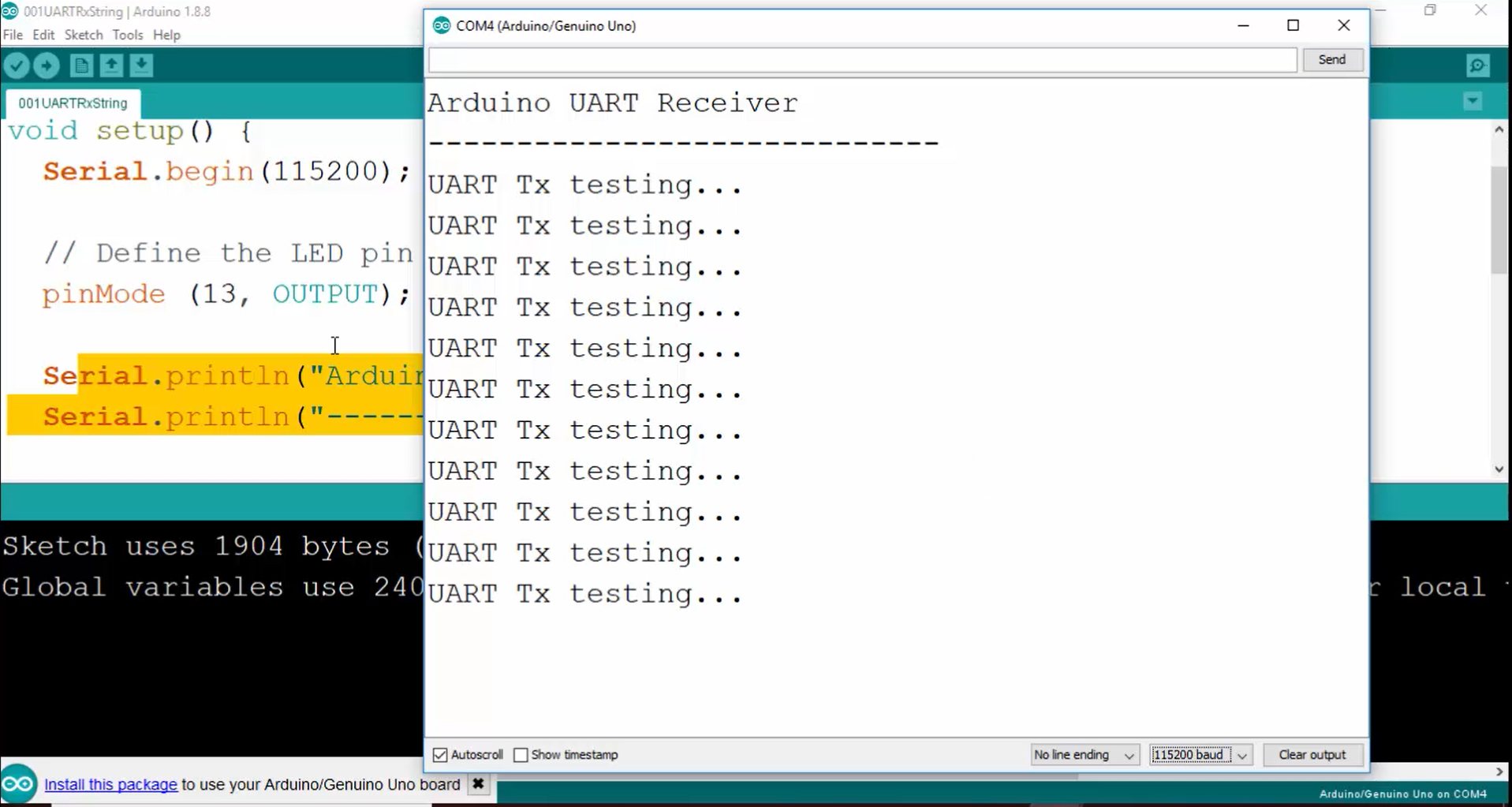
22. Remember that on both sides (the ST side as well as Arduino side), the baud rate must be the same. If there is any mismatch in the baud rate, then the message will not be received properly, and you will start seeing some random characters.
For example, make the baud rate as 9600 on the Arduino side. The ST is sending data at 115200 baud rates, but the Arduino USART peripheral is sampling the RX line at the speed of 9600 and causes the mismatch in the received data samples. That’s why the Arduino board will interpret the data wrongly, and you will start seeing the reception of random characters.
23. Now let’s try the baud rate mismatch condition. Make the baud rate as 9600 on the Arduino side, then compile and upload the code.
24. Open the serial monitor and make the baud rate as 9600 (Figure 23).
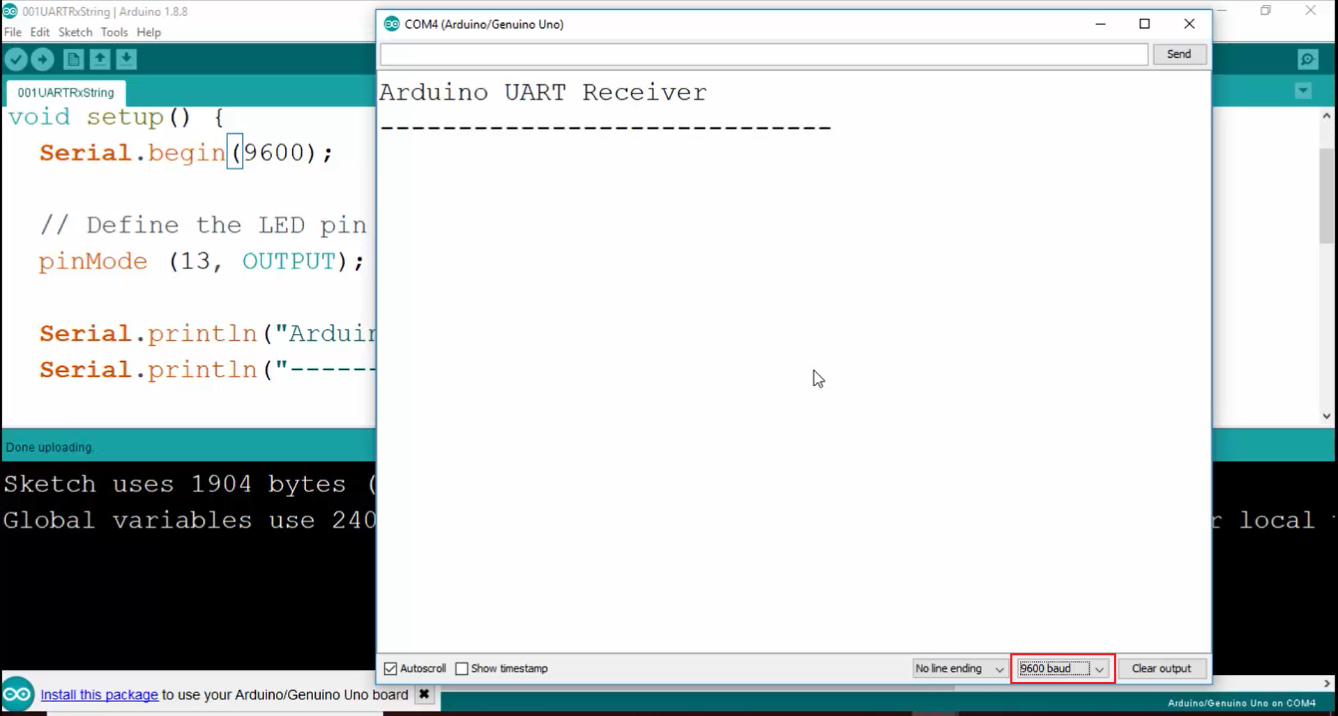
25. Press the user button.
In Figure 24, you can see that the data is not received properly. That is because now the RX engine of the Arduino UART peripheral is actually sampling the RX line at a much lower frequency. Therefore, sampled values will be different, and there will be a mismatch between the transmitted data and received data. That’s why it will receive random characters.
26. Now let’s catch the data on the logic analyzer. Open the logic analyzer and try to capture the data as follows:
a. Use the sample rate as 12 million samples per second and duration as 8 (Figure 24).
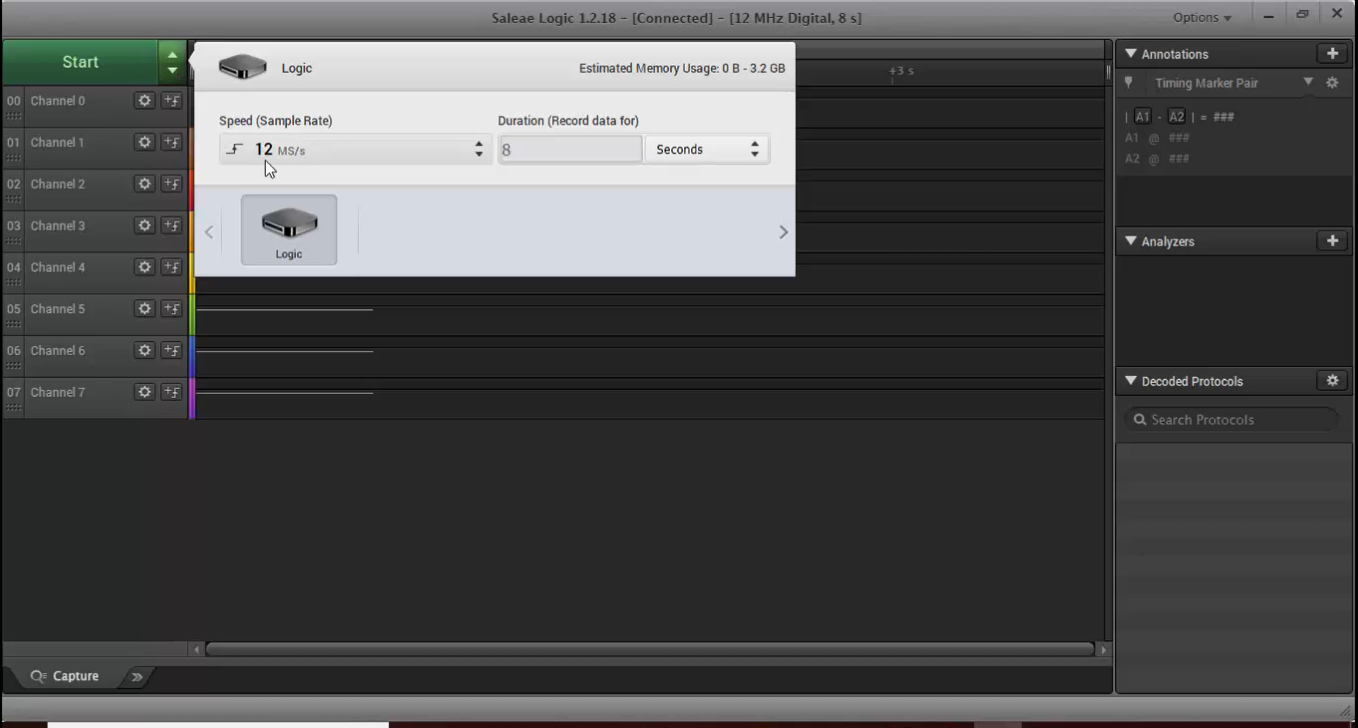
b. Click start and press the user button once.
c. Here channel 0 is STM32 TX, and channel 1 is STM 32 RX. Let’s decode the output shown in Figure 25. For that, go to Async serial (Figure 26) and enter the baud rate as 115200 (Figure 27). Just enter the baud rate if you know. Otherwise, you can use autobaud. Then select the options for the remaining checkboxes as follows (Figure 27):
i. 8 bits per transfer
ii. One stop bit
iii. No parity
iv. The least significant bit is sent first. Because in UART, we always send the least significant bit first.
v. Then select the special mode as none.
After selecting all these options, click on save.
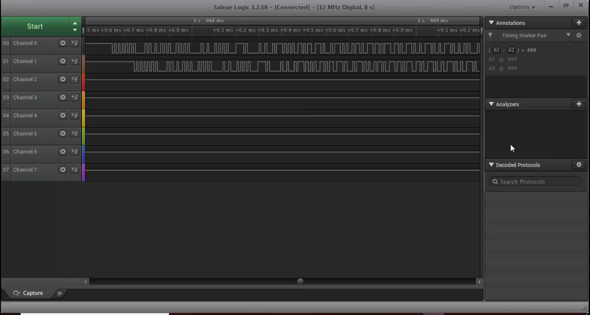
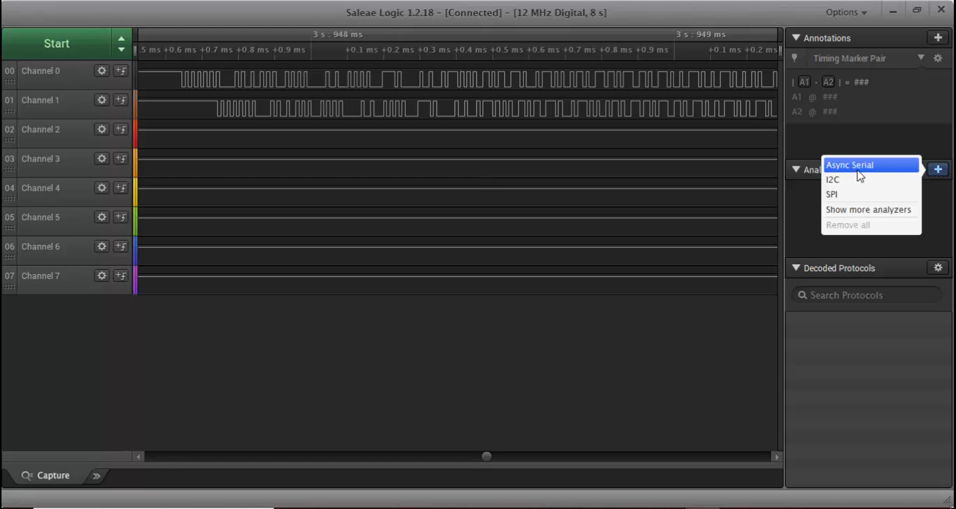
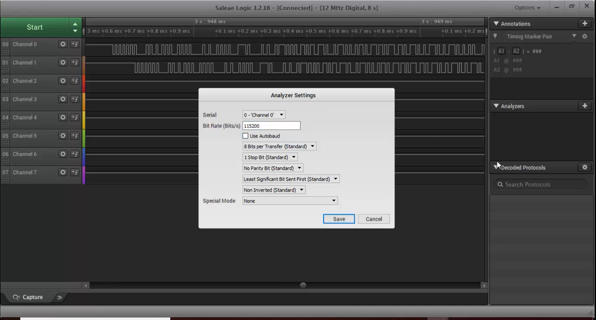
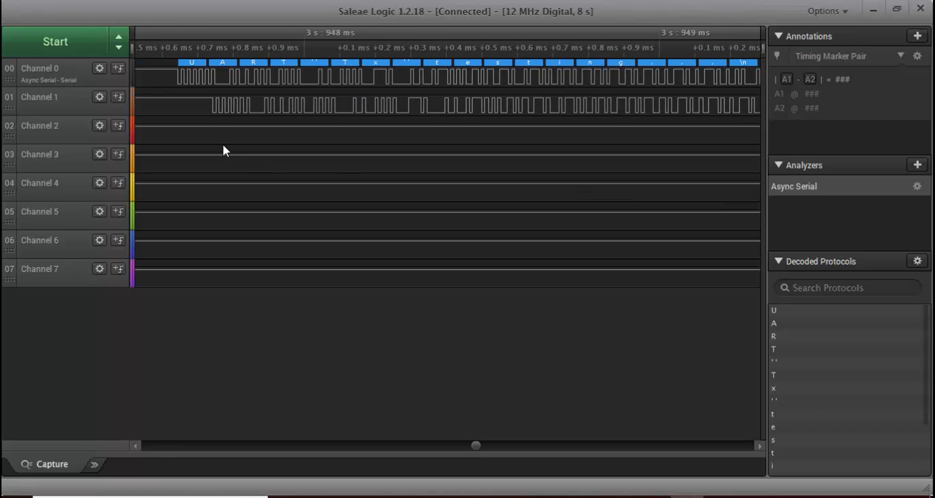
d. Now you can observe the data “UART Tx Testing” in the trace shown in Figure 28, which is exactly the same data that we tried to transmit.
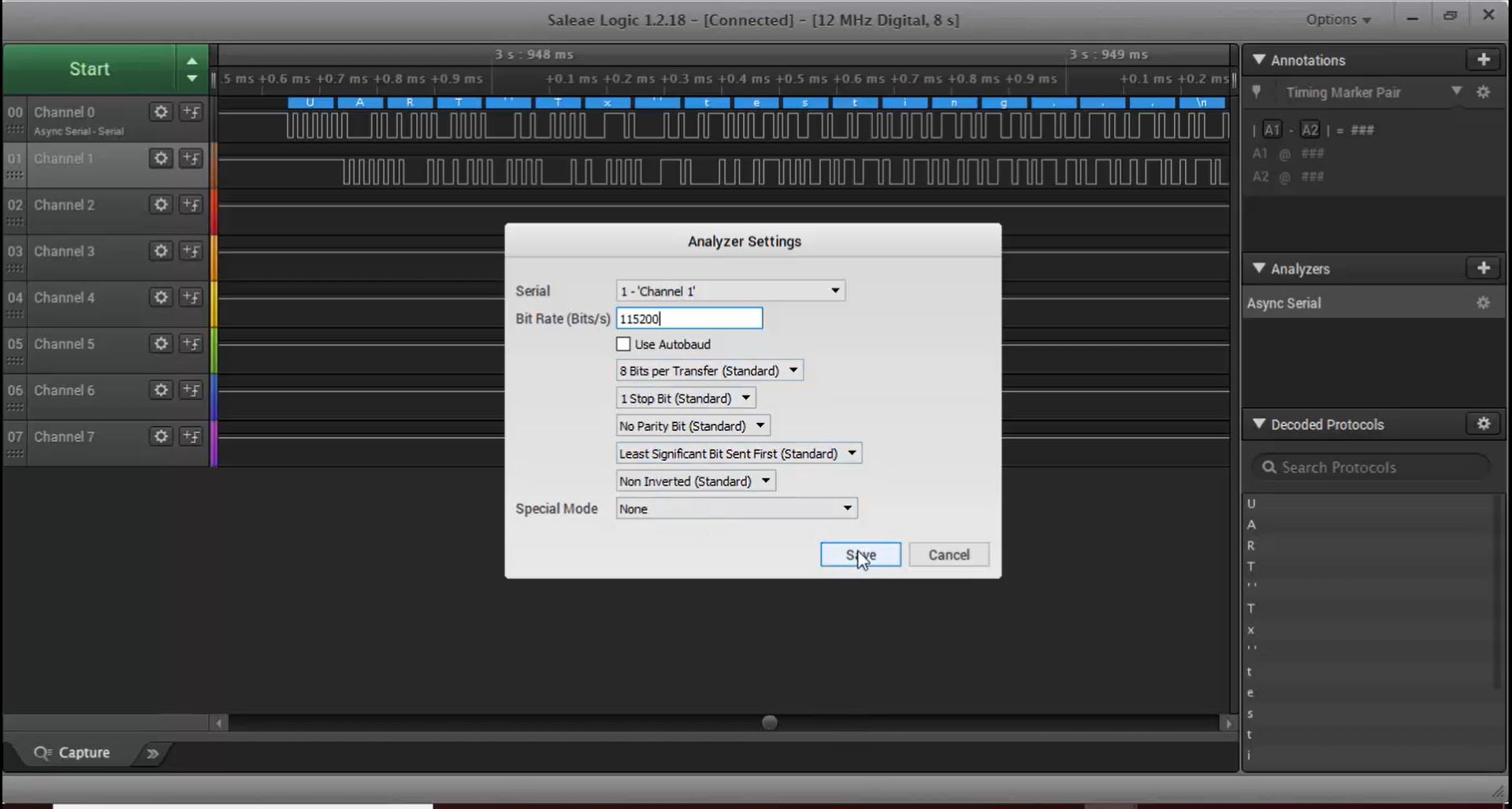
e. Now let’s decode the RX line (Figure 29). Again, select channel 1 and then go to analyzers Async serial (Figure 26). Enter the baud rate as 115200, and all other configurations will be the same as channel 0.
f. From Figure 30, you can see that the data on channel 0 is actually the data sent by the STM32 over its TX line, and the data on channel 1 is sent from the Arduino board on its TX line to the console or serial monitor software.
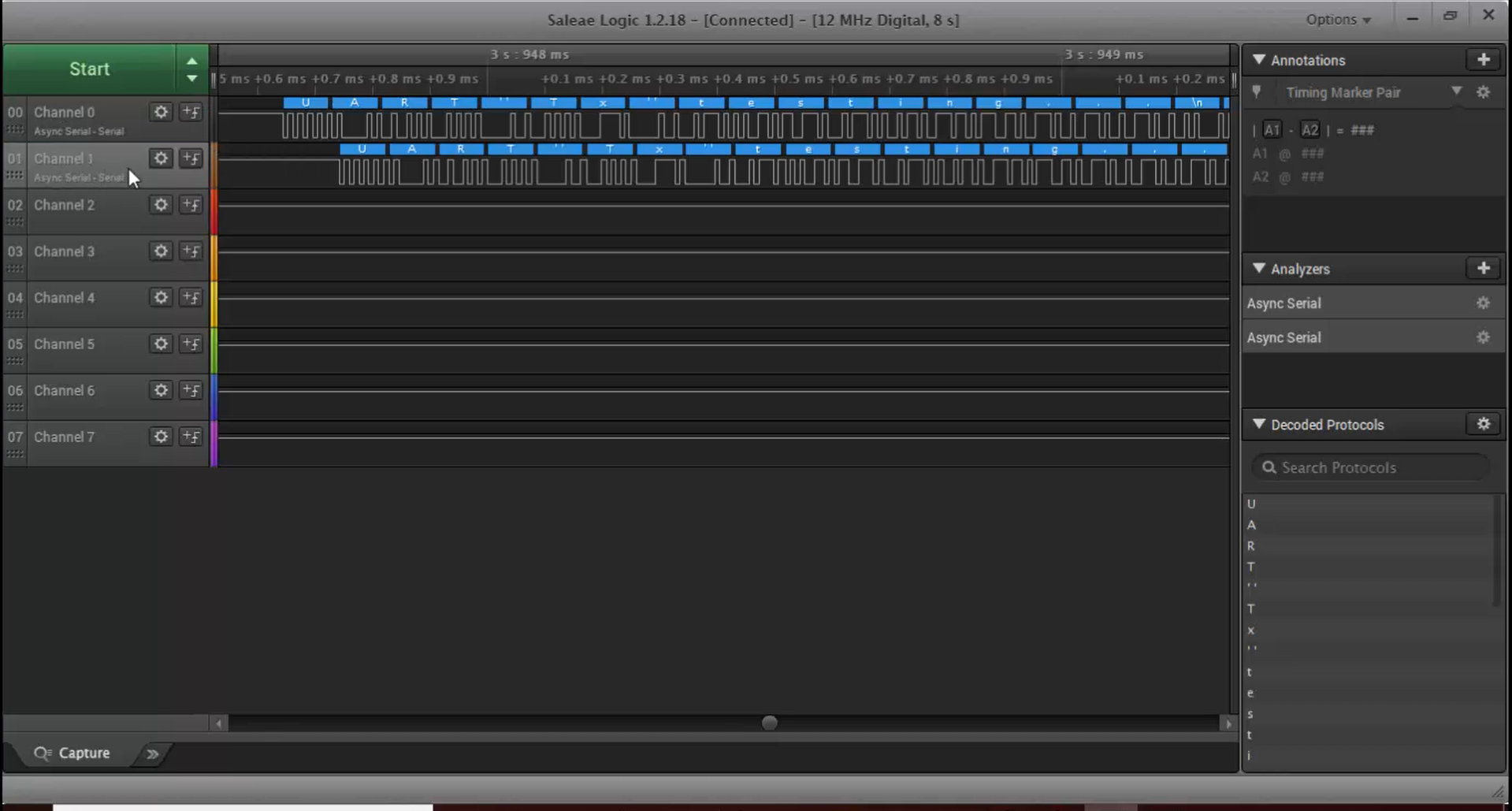
g. After receiving each character from the STM32, the Arduino displays the received character (Figure 31).
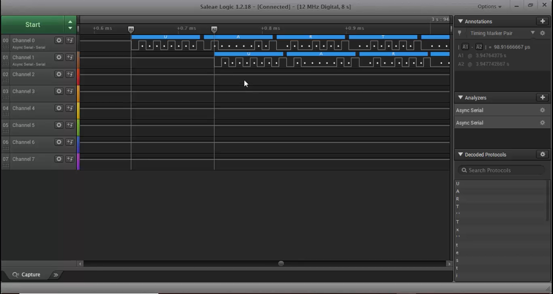
h. Now let’s see how to calculate the baud rate by looking into the waveform shown in Figure 31. It can be calculated as follows:
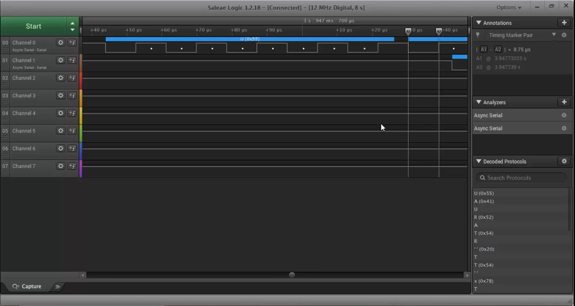
i. While observing Figure 31, you must be seeing the white dots, which is nothing but one-bit time.
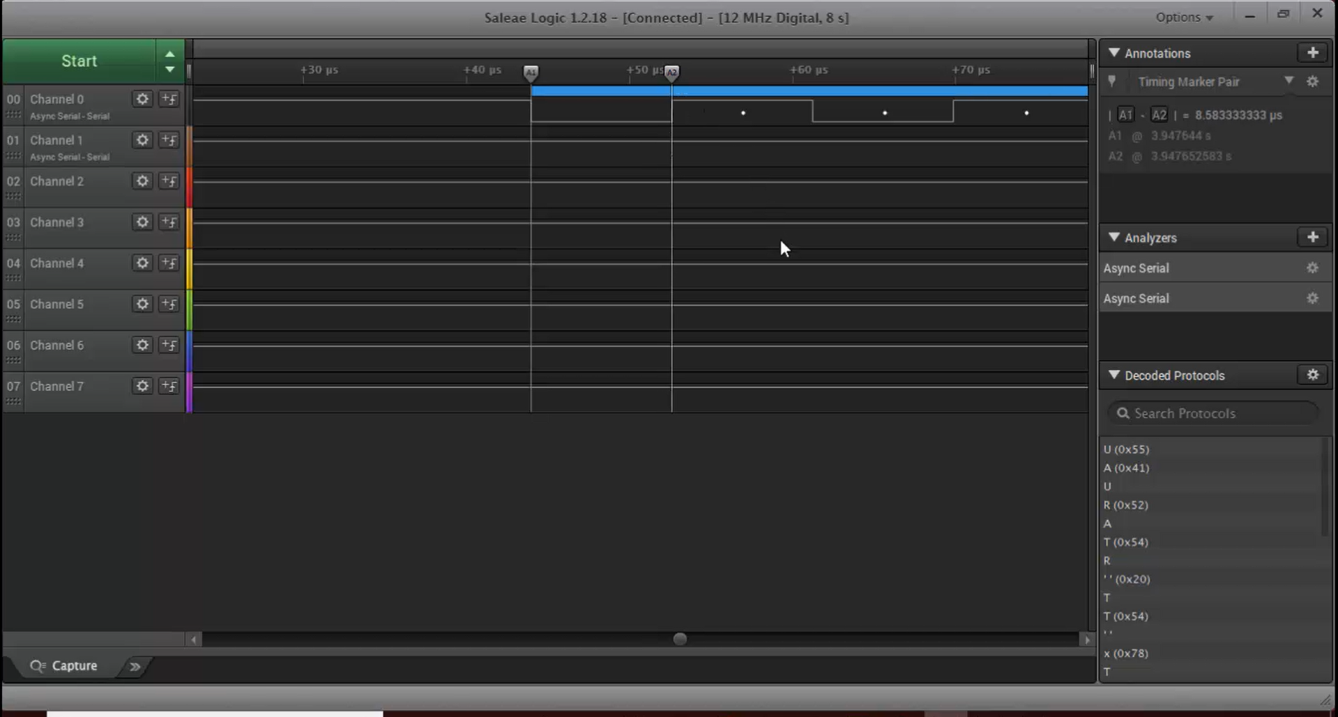
ii. For example, if you want to calculate one-bit time, you have to take the cursor or marker, place it on the white dot, and then place another marker on the next white dot, as shown in Figure 32.
iii. Now, look at the timing marker section. It shows 8.6 microseconds, which is nothing but one-bit time.
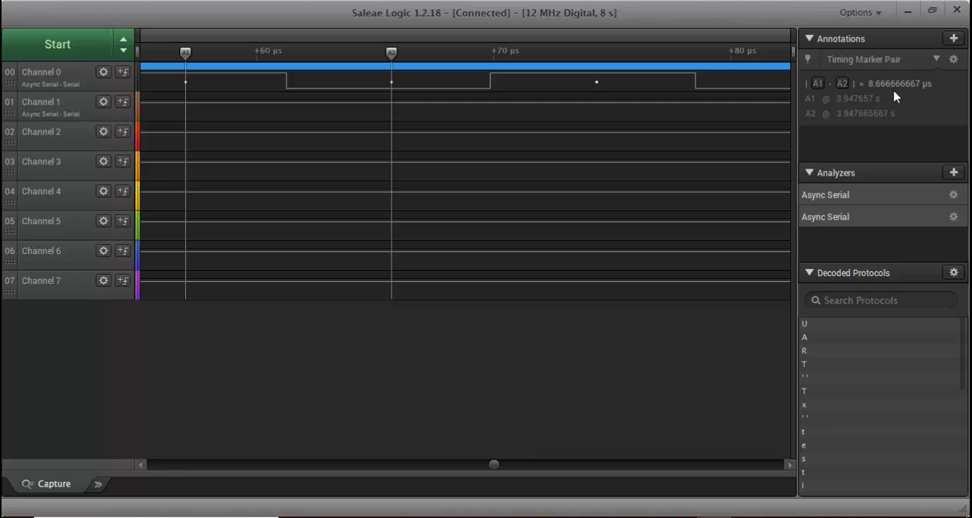
iv. If you divide 1 by 115200, then you will get 8.6 microseconds. That means the amount of time required to send one bit is 8.6 microseconds, which is the same as the value you measured in the logic analyzer.
i. Once the communication ends, you can see that the idle state of the UART TX and UART RX will be high (Figure 33).
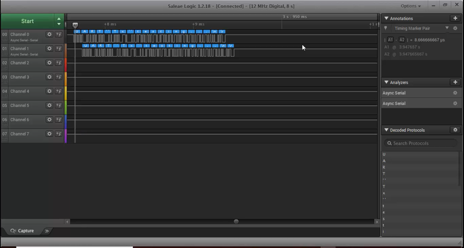
j. The place where the idle line makes its first transition is known as the start bit (Figure 34). The start bit always follows right after the idle line, as shown in Figure 35.
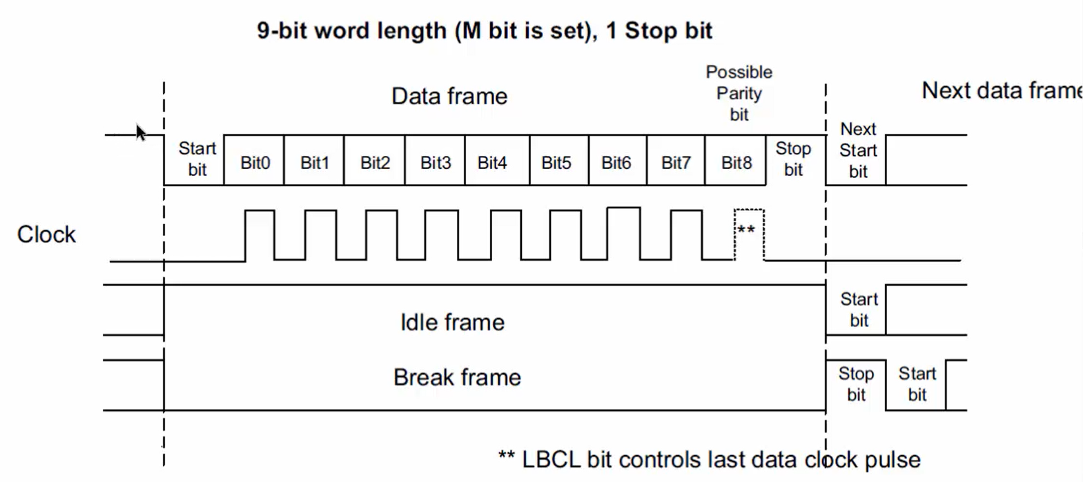
k. After the stop bit, there are 8 bits of user data (Figure 36).
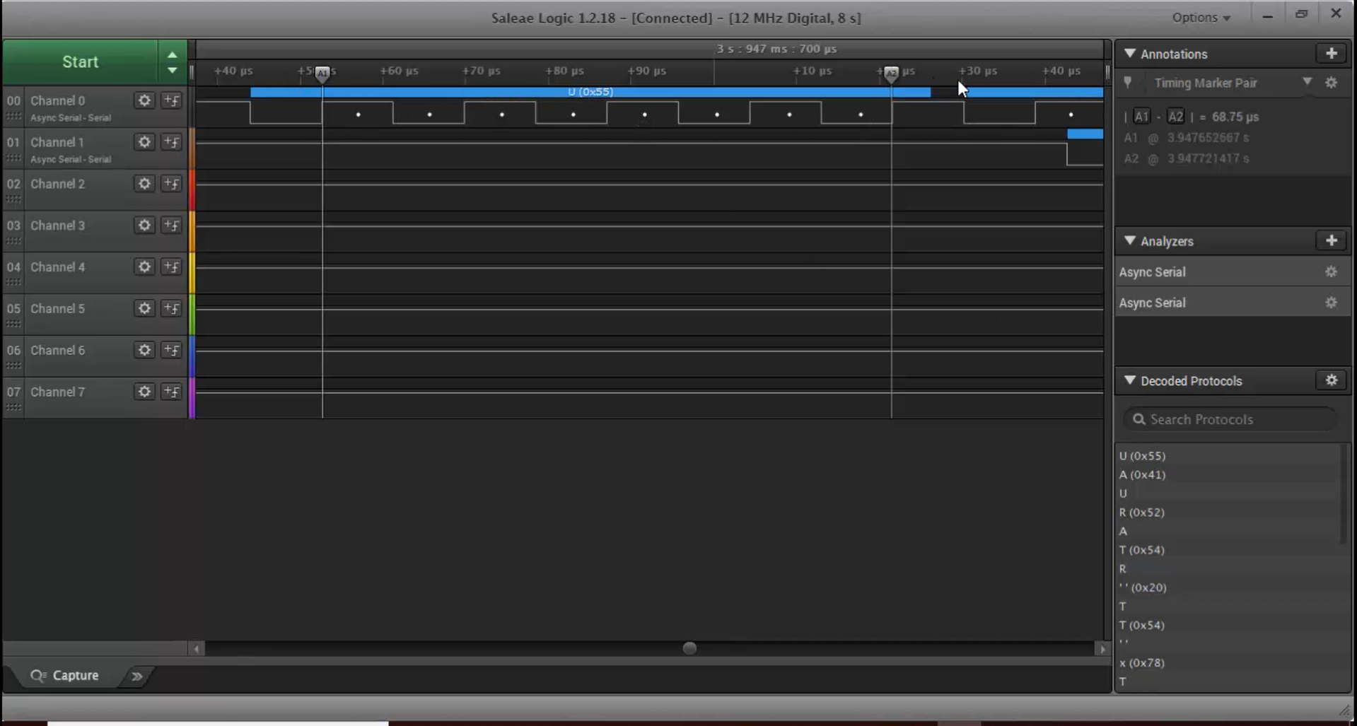
l. You can see one stop bit followed by the user data, as shown in Figure 37.
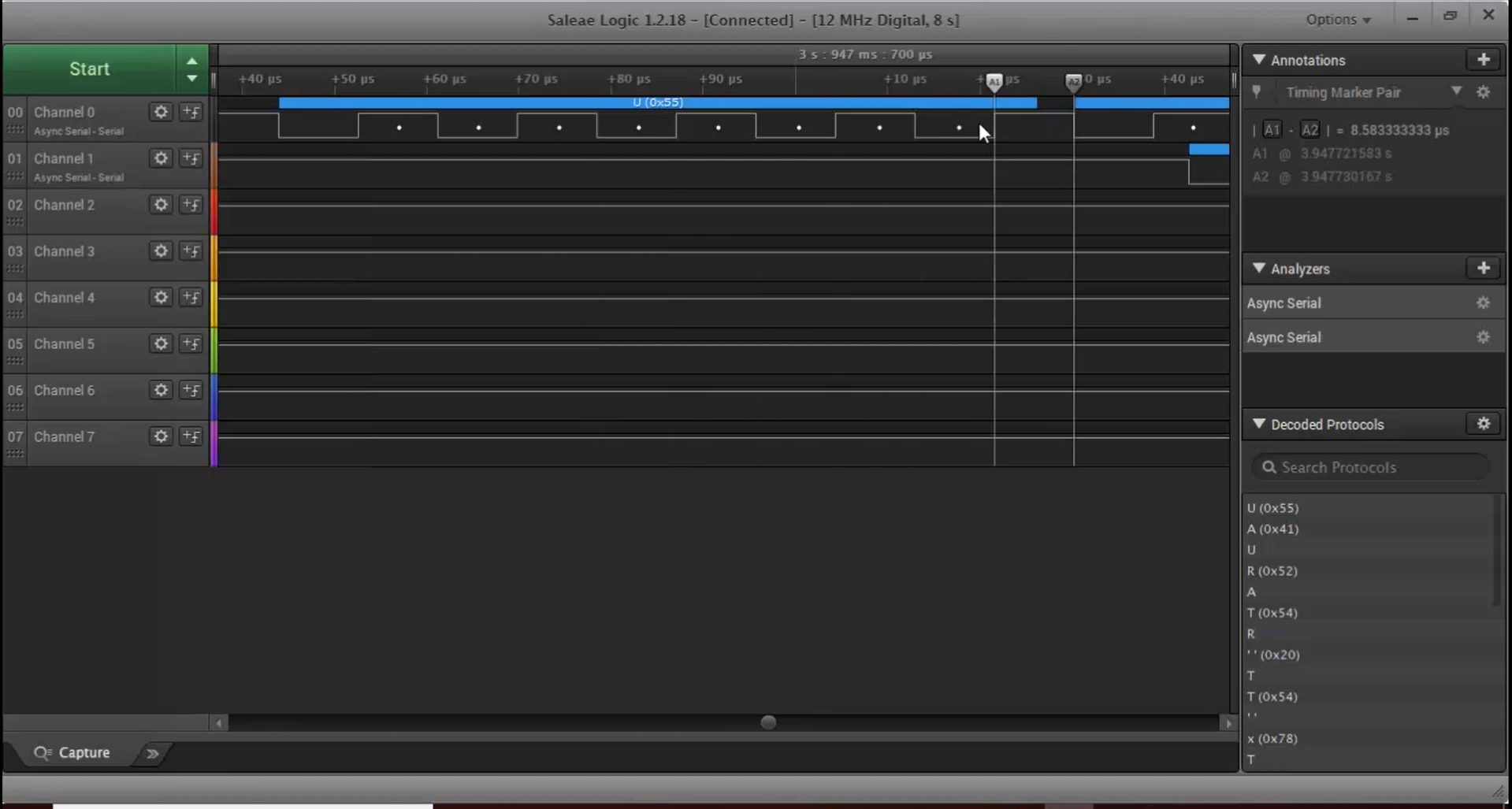
m. After the stop bit, again, you see a high to low transition (Figure 38) that is the start bit of the next frame.
In the following article, let’s see Communicating with PC over UART.
FastBit Embedded Brain Academy Courses
Click here: https://fastbitlab.com/course

