Exercise: Understanding MCU clock configuration Part-2
From Figure 1, you can see that the reset handler begins from line 42. This is the first function or subroutine, which will be called when you reset the microcontroller.

If you trace this reset function, you can see that it is actually called SystemInit (Figure 2). Branch bl branch to SystemInit. The SystemInit is implemented in the system-stm32F4xx.c (Figure 3). This is added by the OpenSTM32 system workbench itself when you create a project.


Now let’s analyze function carefully. Let’s see where it is turning on the PLL. It actually turns on the PLL in the configure the system clock source, PLL multiplier, and divider factors section shown in Figure 4. So, let’s trace SetSysClock() function.

The implementation of the SetSysClock function is as shown in Figure 5. Now let’s check this function. The statement to turn on the main PLL is given in the section called to enable the main PLL (Figure 6). That means this project is by default turning on the PLL. The SetSysClock function is doing so many PLL configurations in order to raise the system clock to 180 MHz. This PLL configuration is not required in our project because our project is a very simple project to print “Hello World”. So, why do we need 180 MHz of system clock? That’s not needed.


Now let’s have a default configuration, i.e., 16 MHz of the system clock. For that, you have to turn off the PLL. Let’s reverse all the configurations or settings, which is done by the SetSysClock.
Steps to get into the default configuration is as follows:
- To do that, let’s take the help of a standard peripheral driver (Figure 7). Just expand the standard peripheral driver, then expand the source and just explore the stm32f4xx_rcc.c (Figure 8). RCC stands for reset and clock control. stm32f4xx_rcc.c is a driver file to handle the RCC engine of the microcontroller. It gives you various APIs in order to manage the clock of your microcontroller.


- In stm32f4xx_rcc.c, you will find an API called RCC_DeInit. First, let’s deinitialize the RCC_Init because that has been initialized with PLL by default code present in our project. Now let’s deinitialize everything, as shown in Figure 9. RCC_DeInit resets the RCC clock configuration to the default reset state. That means it will only turn on the HSI to get the 16 MHz of the system clock, and it will turn off the PLL.

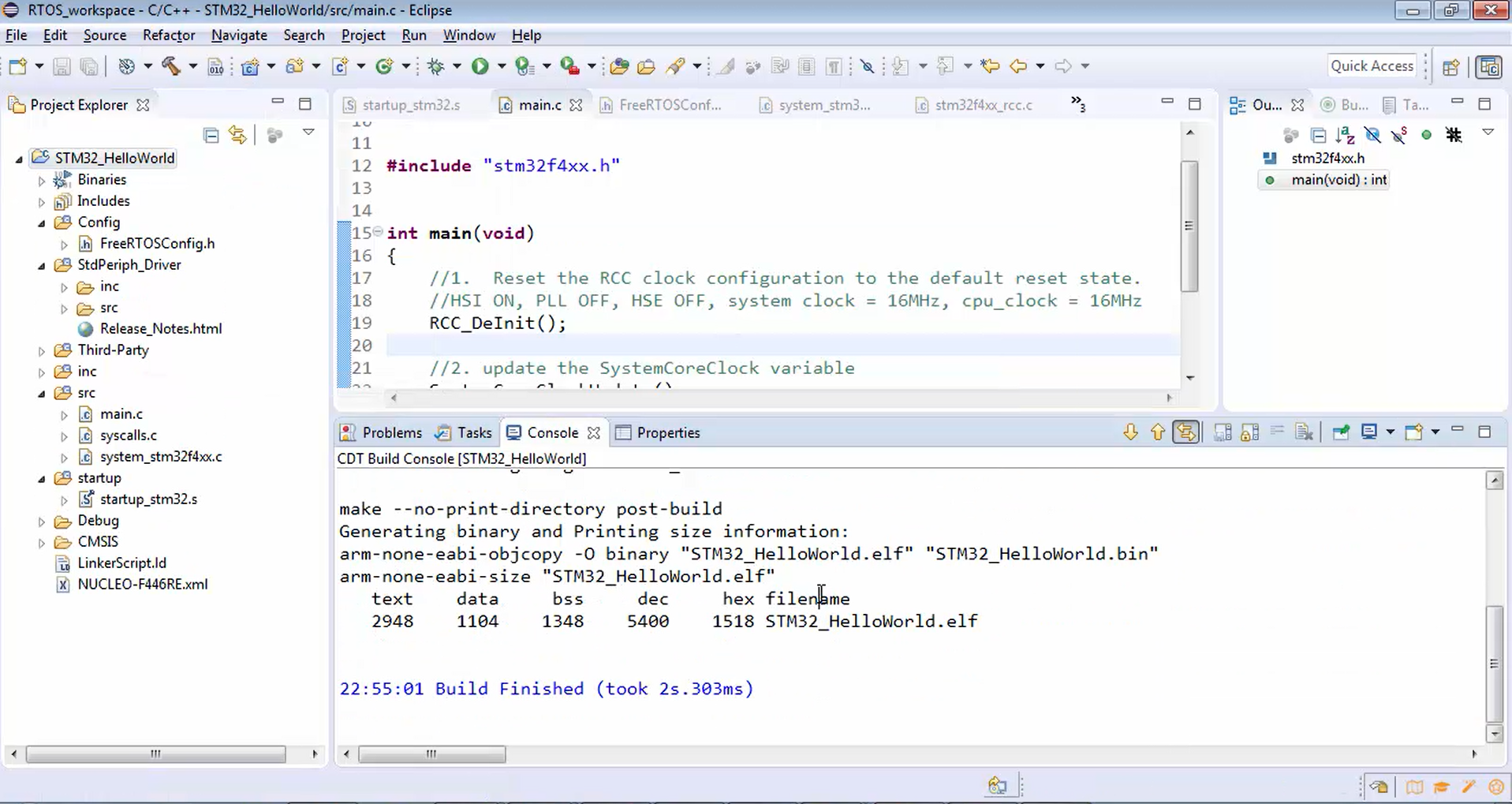
- Let’s use this RCC_DeInit function in our main function. First, reset the RCC clock configuration to the default reset state. For that, you have to call the RCC_DeInit function (Figure 10). This DeInit function turns on HSI, turns off PLL and HSE, and makes the system clock 16 MHz. Now the system clock is 16 MHz. Since you have used DeInit, the AHB prescaler value will be 1, i.e., 16/1 =16. Therefore the clock of 16 MHz will be delivered to the CPU clock. The CPU will be running at 16 MHz.

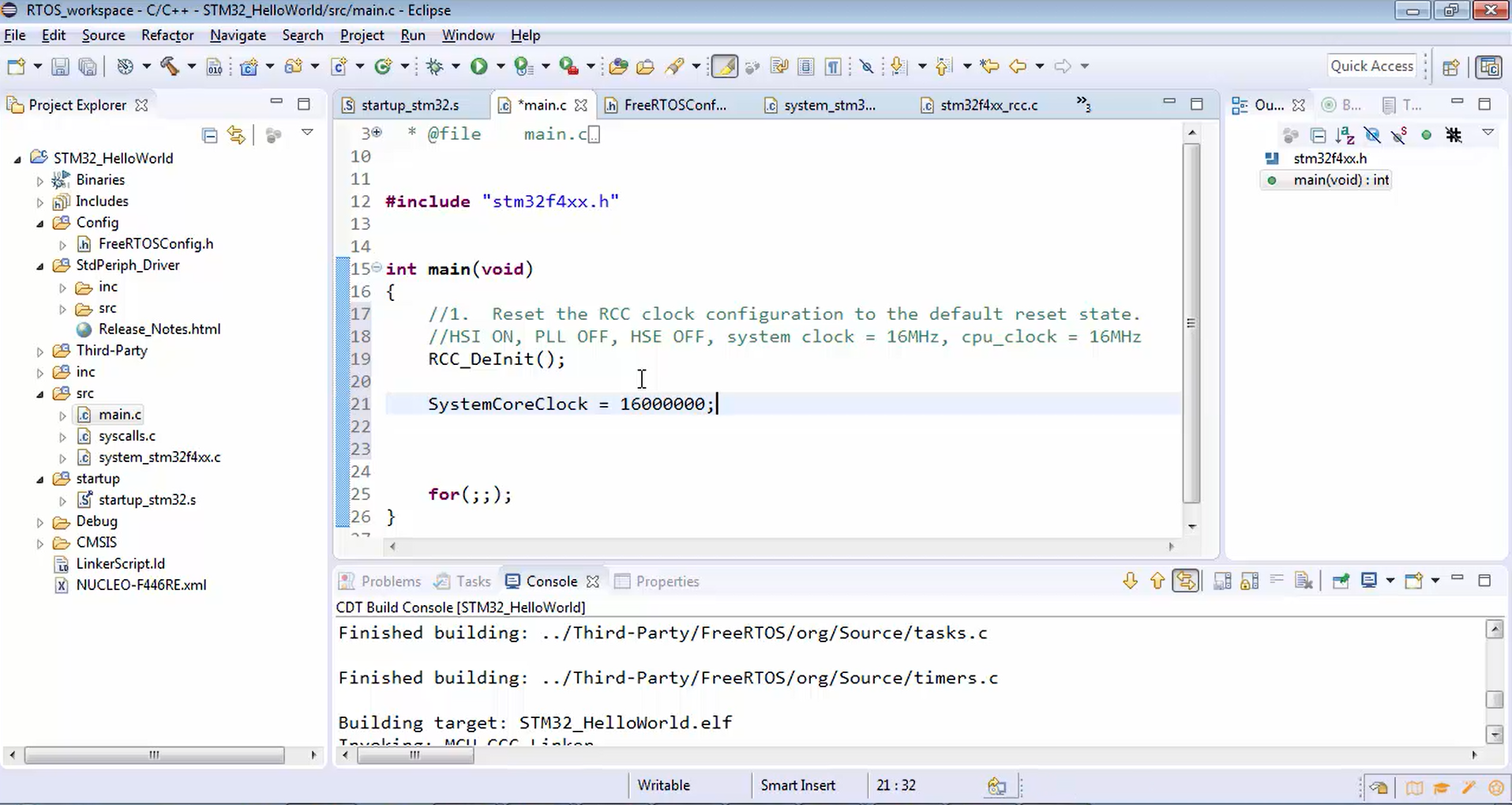
But if you check in the FreeRTOSConfig.h, the SystemCoreClock variable is still pointing to 180 MHz (Figure 11), which is not correct. Now it should point to 16 MHz. That means now you have to update the SystemCoreClock variable. In order to update that variable, either you can directly assign the value for the SystemCoreClock variable, as shown in Figure 12, or you can make use of the SystemCoreClockUpdate function in the system_stm32f4xx.c (Figure 13). Just call this function. It will update the system core clock. It’s better to call the SystemCoreClockUpdate function instead of directly assigning the value.
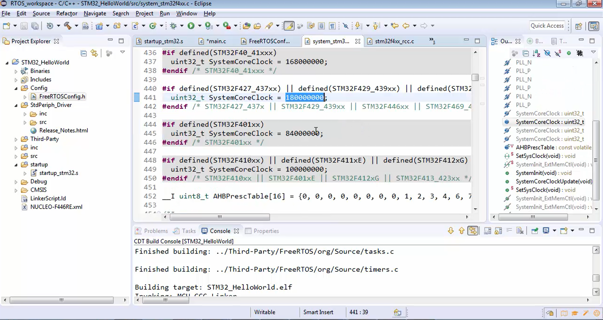
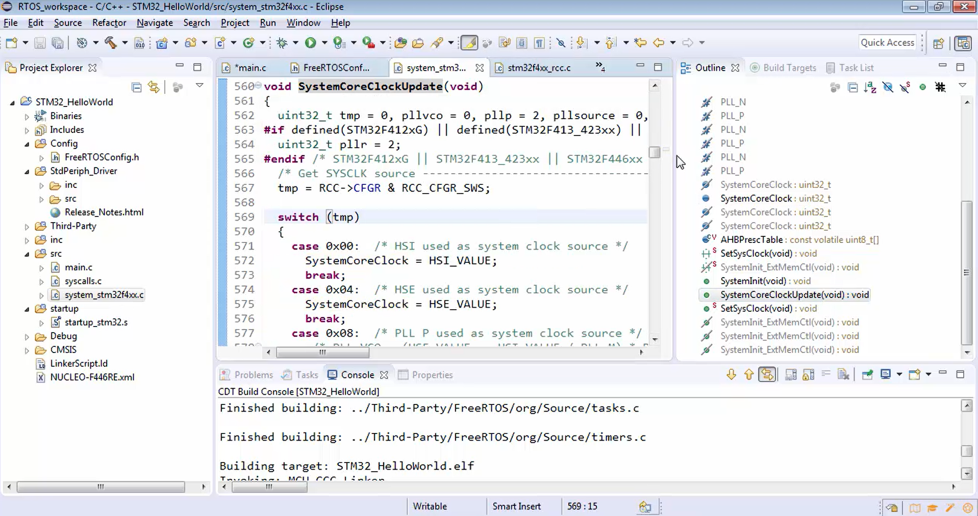
Let’s go to the main.c and update the SystemCoreClock variable (Figure 14).
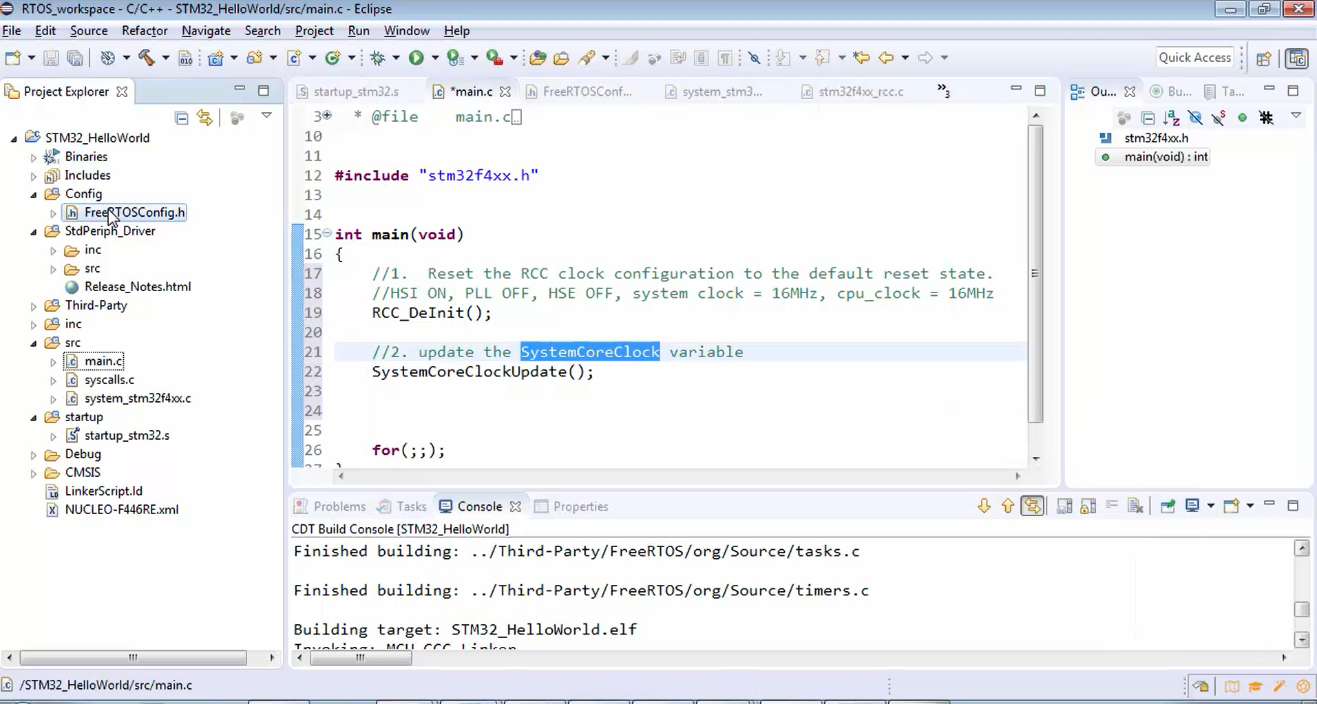
This is a clock initialization. One of the important initializations you have to do in your project is the microcontroller clock settings. Remember that your project will work fine without the deinitialization code, but the CPU clock will be 180 MHz, which is not necessary for this project. If you are ever required to boost the system clock, then you can turn on the PLL, and you can use different frequencies.
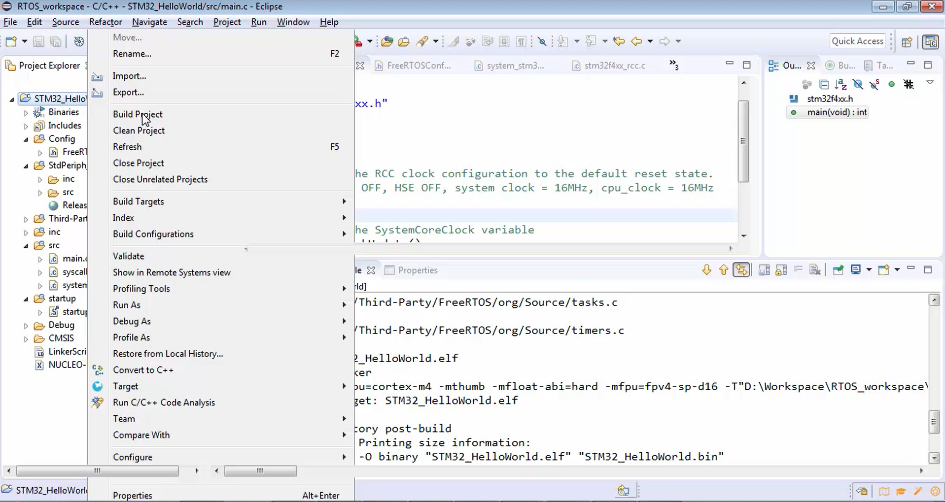
Build the project (Figure 15). In Figure 16, you can see that the project was built successfully.
FastBit Embedded Brain Academy Courses
click here: https://fastbitlab.com/course1

