UML state machine types of Transitions
In UML (Unified Modeling Language), state machine transitions are categorized into different types based on their behavior and conditions.
Transitions:
Transition signifies a change of state or an object’s situation in the object’s life cycle.
Types of Transitions:
Here are the commonly used types of transitions in UML state machines:
- External Transition: An external transition occurs when an event causes a transition from one state to another. It represents a change of state in response to an event triggered from outside the system or from an external source.
- Internal Transition: An internal transition represents a self-transition within a state. It occurs when an event triggers a transition, but the state itself remains unchanged. In other words, the transition stays within the same state.
- Local Transition: A local transition occurs within a composite state. It represents a transition between two substates within the same composite state. It is not visible outside the composite state and is used to model internal behavior.
- Self-transition: A self-transition represents a transition from a state back to the same state. It is useful when there are specific actions or events associated with returning to the current state.
- Transition with a Guard Condition: A transition can have a guard condition associated with it. A guard condition specifies a condition that must be true for the transition to be taken. It is represented by a Boolean expression, and the transition occurs only if the guard condition evaluates to true.
- Transition with a Trigger Event: Transitions can be triggered by specific events. The trigger event represents an occurrence or stimulus that causes the transition to take place. Events can be internal or external, and they can have parameters associated with them.
- Transition with a Effect: A transition can have an associated effect, which represents the actions or behaviors that occur when the transition is taken. The effect can be a single action or a set of actions performed during the transition.
These are some of the common types of transitions in UML state machines. They provide flexibility in modeling the behavior and dynamics of a system by capturing the state transitions and associated conditions or actions.
In the previous article, we explore the internal activities and the ‘entry,’ ‘exit,’ ‘do’ all these internal activities of a state. Now let’s understand the internal transition.
Internal transition
- Each item has the following syntax
{<trigger>}* [‘[‘ <guard>’]’] [/<behavior-expression>]
- If the event occurrence matches the ‘trigger’ and ‘guard’ of the internal transition evaluates to be TRUE, then behavior identified by < behavior-expression> will be executed without exiting or re-entering the state in which it is defined.
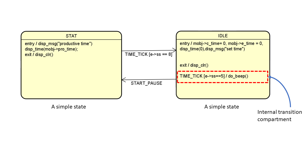
Look at Figure 1, it is one example of Internal transition. We have a state called IDLE. In this compartment, the red color line shows the internal transition compartment. All the internal activity entries are mentioned first, and then the internal transition compartment.
In this example, TIME_TICK is a ‘trigger,’ [e->ss==5] is the ‘guard,’ and do_beep is the ‘action.’
When the ‘trigger’ happens or when the ‘event’ happens in the system, and if the ‘guard’ turns out to be TRUE, then only the action will be taken without exiting or re-entering the state. There is no exit from the state. So, that’s what we call the internal transition.
TIME_TICK [e->ss == 5]/ do_beep()
This statement says that whenever the TIME_TICK happens and if some variables value is 5, then do a beep. That’s it.
Internal : internal is a special case of a local Transition that is a self-transition (i.e., with the same source and target States), such that the State is never exited (and, thus, not re-entered), which means that no exit or entry Behaviors are executed when this Transition is executed.
This kind of Transition can only be defined if the source Vertex is a State [OMG® UML 2.5.1]
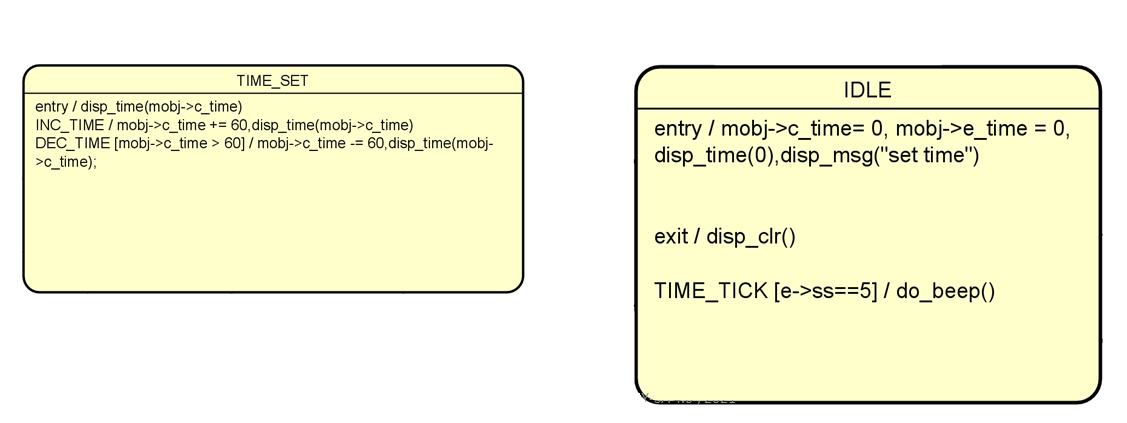
In this example(Figure 2), TIME_TICK, INC_TIME,DEC_TIME are an internal transition.
External Transition:
- In external transition, the source state is exited due incident of a trigger, the optional action associated with the transition is executed followed by execution of exit action of the state
- An external transition signifies a change of state or an object’s situation in the object’s life cycle.
- When the state is changed, now the object is ready to process a new set of events and execute a new set of actions.
- Transitions are denoted by lines with arrowheads leading from a source state to a target state
Example Tranistion
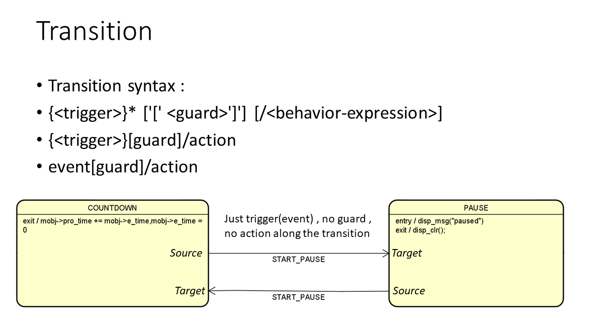
When the object’s current state is COUNTDOWN and if the event START_PAUSE is received, then the object transitions to state PAUSE(updates its state to PAUSE).
Transition in a program is nothing but updating a state variable. One a variable state changes to PAUSE.

After the Transition, the exit action of the COUNTDOWN state will be executed—exit action of the source state.
Look at figure 4, T represents the trigger or just an event. There is no guard condition, and there is no action, such transitions are possible; the guard and these actions are all optional, even the trigger is optional. So, any combination could be possible.
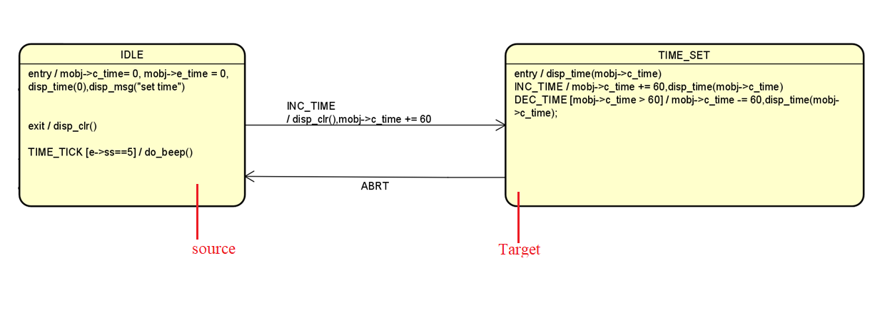
Consider this example(figure 5), and here there are two states, IDLE and TIME_SET. Let’s assume the object is currently in the IDLE state, and when it is in the IDLE state, the INC_TIME event happens. If this event happens, there is no guard condition, so the object has to exit from the IDLE state and go to the new state, i.e., TIME_SET.
As per the UML specification, first, the object has to exit from its current state. In this case, the object has first to exit the IDLE state. Exit means completing its exit actions. When the exit actions are completed, that means the object has safely exited from its state.
That’s why first, the exit action will be executed. Second, INC_TIME will be executed, followed by the execution of the transition action, and third, followed by executing the entry action of the newly entered state. That’s how the transition takes place. This is also mentioned in the UML specification.
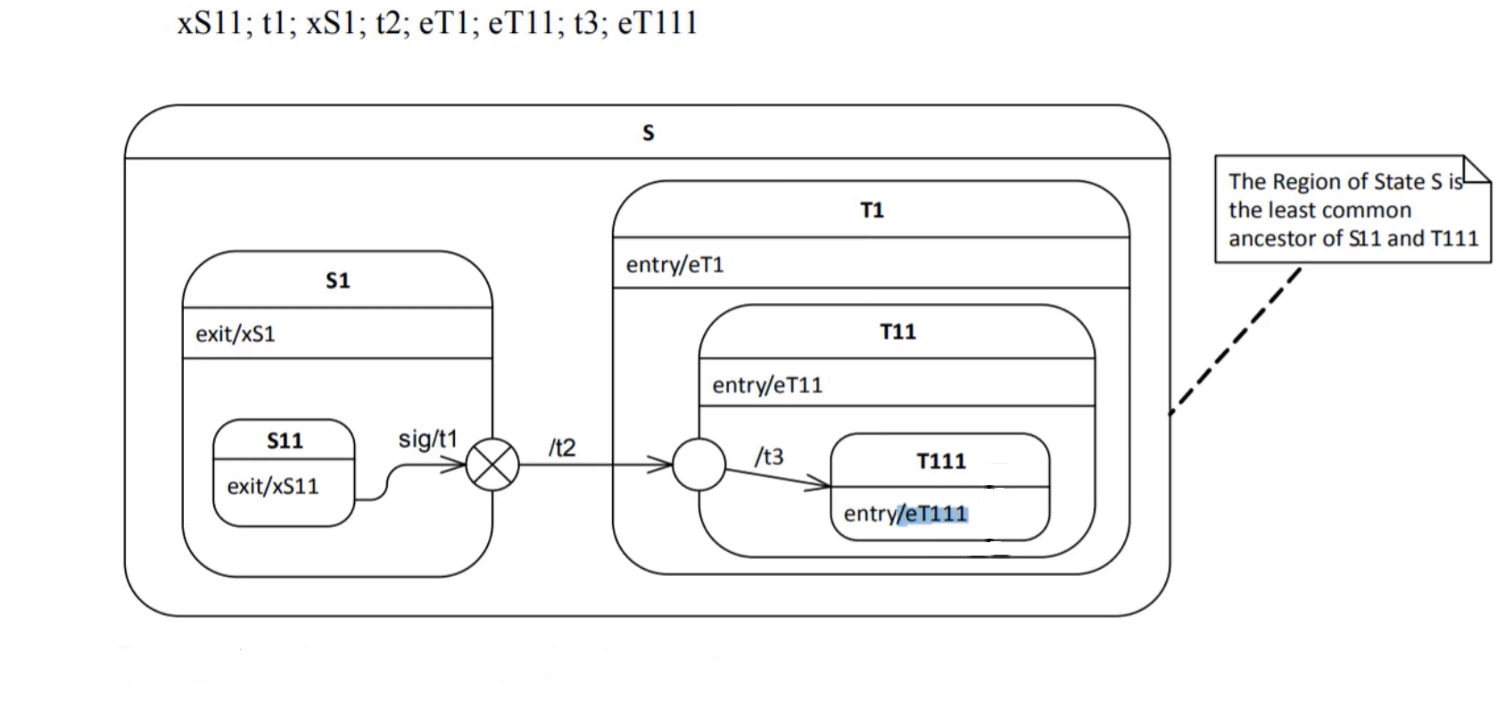
Figure 6 shows the compound transition example. Here, S11 is a simple state. Let’s assume that the object is currently in an S11 simple state, and the trigger happens; the trigger is ‘sig .’ When ‘sig’ happens, the object has to leave the S11 state.
xS11;t1;xS1;t2;eT1;eT11;t3;eT111, this is an order of execution of actions.
First, xS11 is executed. xS11 is nothing but its exit action executed first followed by the transition action t1. The t1 is executed next. And after that, it goes out of this composite state S1. So, S1 is a parent, or it’s a super state of S11. Exiting this composite state also means exiting from this S1 composite state. That’s why the exit action of the S1 state is executed. That is xS1 here.
The exit actions are executed right from the innermost state as per the specification. S11 is an innermost state. So, exit actions are executed beginning from the innermost state to the outermost state. And after that, it goes to the exit point.
And after that, it goes to t2. And now it enters the new composite state, t1, and its target is T111. That’s the target state. Before reaching the target state, it has to go through all other intermediate states, and it executes all the entry actions which come along the way. First it executes the entry action eT1,eT11,t3 (that’s a transition action), and eT111.
From this picture, you can understand that the actions executed are right from the outermost state towards the innermost state during entry into a composite state. Exiting a composite state involves executing exit actions from the innermost state towards the outermost state.
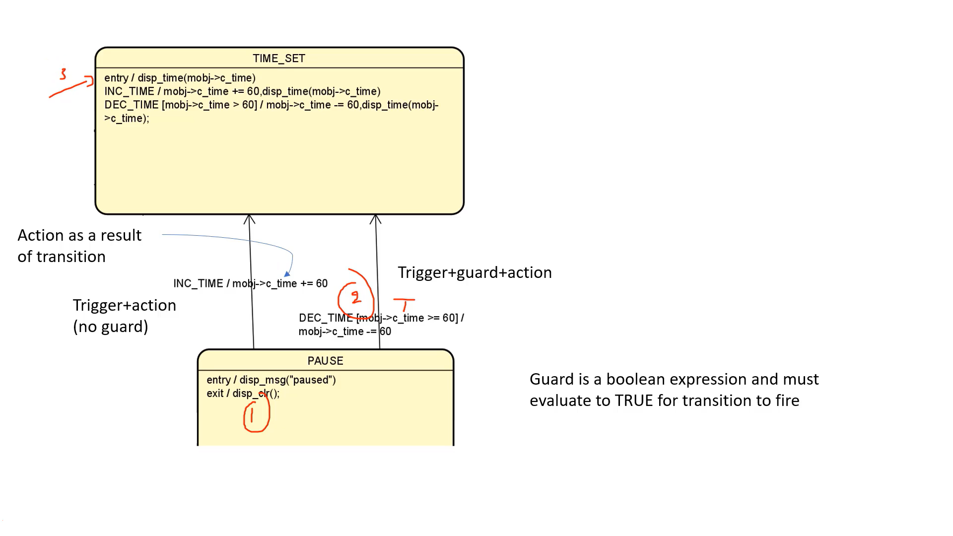
Let’s see one more example. Let’s consider Figure 6. Let’s assume the object is currently in a PAUSE state, and the decrement time event happens. When a DEC_TIME event happens, it is guarded by the guard condition–(2). Guard condition is written inside the square brackets. And Guard is nothing but it’s a Boolean expression and must evaluate to TRUE for transitions to fire. If this condition becomes TRUE, then only the transition will fire. That means, first, the exit action will be executed–(1), then the transition actions–(2), then the entry actions–(3), only if the Guard condition is evaluated to be TRUE.
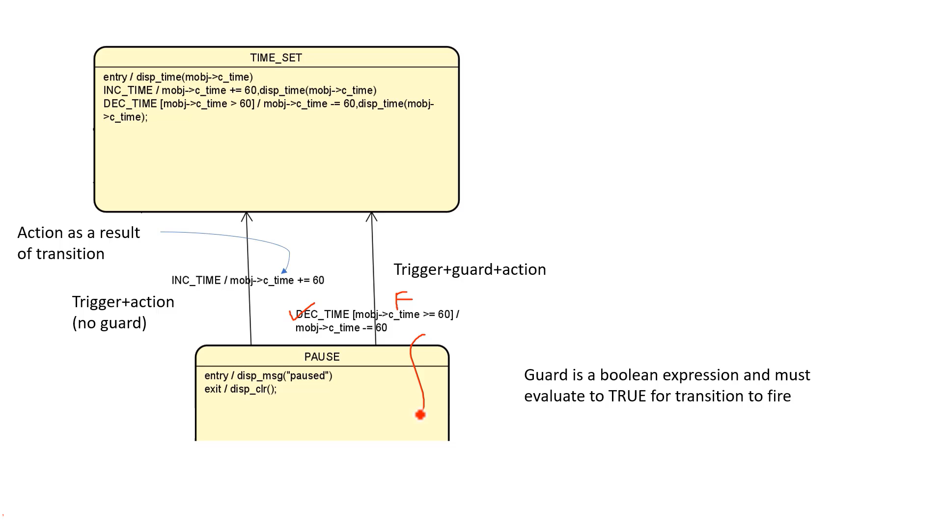
If the Guard condition evaluates to FALSE, if the DEC_TIME event happens, there is no transition. The object will not leave the state. So, no exit from the state. No exit means no execution of transition actions. No entry to the new state. It’s just like this event is ignored.
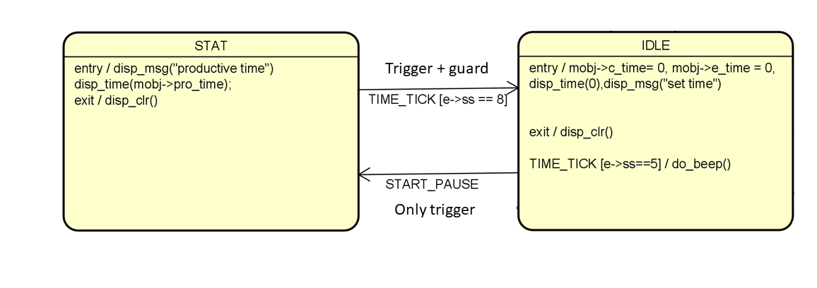
And sometimes, an external transition may happen just because of a trigger. The guards and the transition actions are optional. Look at Figure 9; there is a trigger, only trigger. That may also cause the transition.
And sometimes transition may happen just because of trigger and guard. The transition guard may be absent. Whenever the TIME_TICK event happens, the transition happens only if the guard condition evaluates to be TRUE.
Local transition:
- Local: local is the opposite of external, meaning that the Transition does not exit its containing state (and, hence, the exit Behavior of the containing State will not be executed). However, for local Transitions, the target Vertex must be different from its source Vertex. A local Transition can only exist within a composite State. [OMG® UML 2.5.1]
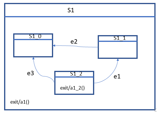
In the diagram(figure 10), you are seeing S1, which is a composite state. And this composite state has three substates. S1_0, S1_1,S1_2 are 3 substates and e1, e2, e3 are local transitions of S1.
Few Points to remember:
- doActivity behavior commences execution when the state is entered only after the state entry behavior has completed
- entry , exit , do , cannot be associated with any transitions
FastBit Embedded Brain Academy Courses
Click here: https://fastbitlab.com/course1

