Exercise-003 Button software de-bouncing implementation
In this article, we will implement software button debouncing.

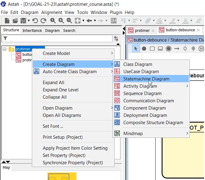
Just right-click over the project and go to Create diagram and Statemachine diagram(shown in Figure 1); you can do that.

A state machine diagram can represent pins in different states, as shown in Figure 2.
We will not implement this as a standard UML specification-based state machine. We will implement this as a normal function, but I just wanted to let you know that the pin debouncing can also be represented in a state machine diagram.
Here, we have got three states. NOT PRESSED, PRESSED, and BOUNCE. Assume that this is implemented as a function, and the function receives the button pad value.
First, the pin will be in the Not pressed state, and when the button pad value is non-zero, that means someone has pressed the buttons. So, there will be a Transition to a bounce state. And the action is set_curr_time.
But the key point here is that when the pin is in the Not pressed state and if the button pad value becomes non-zero, the state machine moves to the Bounce state. And in the Bounce state, it has to wait for 50 milliseconds, so that’s the bounce period. 50 milliseconds is spent here. The beginning of that 50 milliseconds is marked by this set current time. So, we can do this using millis().
While the state machine is in the Bounce state, after 50 milliseconds, it has to re-verify the button pad value once again (the fresh button pad value). If it is 0, that means no one has pressed the button. That’s why it goes to a Not pressed state. But if the button pad value is non-zero after 50 milliseconds, it goes to the Pressed state. That indicates someone has really pressed the button.
And while it is in the Pressed state, it stays there until the button pad value returns to 0.
When someone releases the button, the button pad value becomes 0, which indicates that someone has released the button. That’s why the Transition value comes to a bounce state again. Because you have to debounce the release state also. And the beginning of the time is marked by the set_curr_time function.
Now we will implement this as a small function. Let’s go to the code. We will create another enum in main.h— typedef enum as shown below.
typedef enum{
          NOT_PRESSED,
          BOUNCE,
          PRESSED
}button_state_t;
create enum function in main.h
static uint8_t process_button_pad_value(uint8_t btn_pad_value)
{
   static button_state_t btn_sm_state = NOT_PRESSED;
   static uint32_t curr_time = millis();

   switch(btn_sm_state){
    case NOT_PRESSED:{
     if(btn_pad_value){
       btn_sm_state = BOUNCE;
       curr_time = millis();
      }
     break;
}
Case NOT_PRESSED state
We have already defined a function process_button_pad_value; inside this, we will do that. First, I will take a variable static button_state_t btn_sm_state = NOT_PRESSED. And we will take one more variable here to store the current time static uint32 curr_time = millis();
Now let’s use the switch case. switch(btn_sm_state). Let’s write different cases for NOT PRESSED, BOUNCE, and PRESSED states.
When it is Not pressed, the statemachine says that if the btn_pad_value is non zero, there is a transition. Here we have to set the current time. That will be used in the BOUNCE state to timeout after 50 milliseconds. After that, we have to put a break statement (Figure 1).
 case BOUNCE:{
    if(millis() - curr_time >= 50 ){
       //50ms has passed
       if(btn_pad_value){
         btn_sm_state = PRESSED;
         return btn_pad_value;
        }
        else
          btn_sm_state = NOT_PRESSED;
     }
     break;
 }

 case PRESSED:{
    if(!btn_pad_value){
      btn_sm_state = BOUNCE;
      curr_time = millis();
    }
    break;
}

}
return 0;
}
Case BOUNCE and PRESSED state
When it comes to the BOUNCE, it should not do anything until the 50 milliseconds passes. That’s why let’s do nothing until 50 milliseconds passes (shown in Figure 2).
Now, here I recheck the button pad value. So, if(btn_pad_value),if it is set, then go to Pressed state. btn_sm_state = PRESSED; else btn_sm_state = NOT_PRESSED; and then break;
While it is in the PRESSED state, if btn_pad_value is 0, it must go to the BOUNCE state. And since it is going to the Bounce state, you have to reinitialize the current time. Because this marks the starting point, the 50 milliseconds are recalculated. So, millis(). Put a break statement.
And also process_button_pad_value function returns something. See Figure 5, If it is really Pressed, if the process_button_pad_value function decides that after 50 milliseconds, something has really Pressed, then it has to return the btn_pad_value.
Because this btn_pad_value is a value after the software debounces, after waiting for 50 milliseconds, that’s why let’s return that value back to the caller.
And process_button_pad_value function by default returns 0.
void setup() {
   // put your setup code here, to run once:
   Serial.begin(115200);
   display_init();
   Serial.println("Productive timer application");
   Serial.println("===========================");
   pinMode(PIN_BUTTON1,INPUT);
   pinMode(PIN_BUTTON2,INPUT);
   pinMode(PIN_BUTTON3,INPUT);

   protimer_init(&protimer);
}
setup() function
Now let’s give attention to implementing the lcd.c and lcd.h files. That will be our last implementation, and after that, we can test it.
First of all, we will write the setup function. In the setup function, we have to do various setups.
- Serial.begin(115200); If you are printing anything on a serial monitor, it is required.
- And after that, we will print something. Serial.println(“Productive timer application);
- After that, we will use the pinMode function of Arduino to configure the mode for the buttons. And now, let’s use this pinMode(PIN_BUTTON1, INPUT); You have to do it three times.
- And after that, you call protimer_init(&protimer); function.
And in the upcoming article, we will explore the Arduino LCD library and try to use the Arduino LCD library methods in our project to drive our 16X2 LCD. And after that, we will test this project on the hardware.
pinMode()
Syntax: pinMode( pin, mode)
As you know, for the pinMode function, you have to provide ‘pin,’ and ‘mode.’ Mode is nothing but any of these values→ INPUT, OUTPUT, INPUT_PULLUP. INPUT_PULLUP option is already available, so you need not use the external pullup resistors. But using external pullup resistors is usually generic because sometimes we don’t know whether the microcontroller pin supports the internal pullup. So, you have to do more investigation on that pin. But, if you don’t want to use those resistors of 10 kiloohms, you can use the option INPUT_PULLUP.
FastBit Embedded Brain Academy Courses
Click here: https://fastbitlab.com/course1


