Exercise-008:Implementation part 8
In the previous article, we implemented the alarm state machine as well as the button machine. It is not yet over, so we have to take care of our clock alarm state machine.
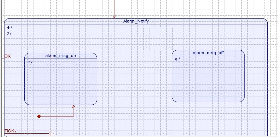
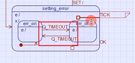
You see this error state in the clock alarm state machine (Figure 1). There are some missing links. So, we have to draw that.
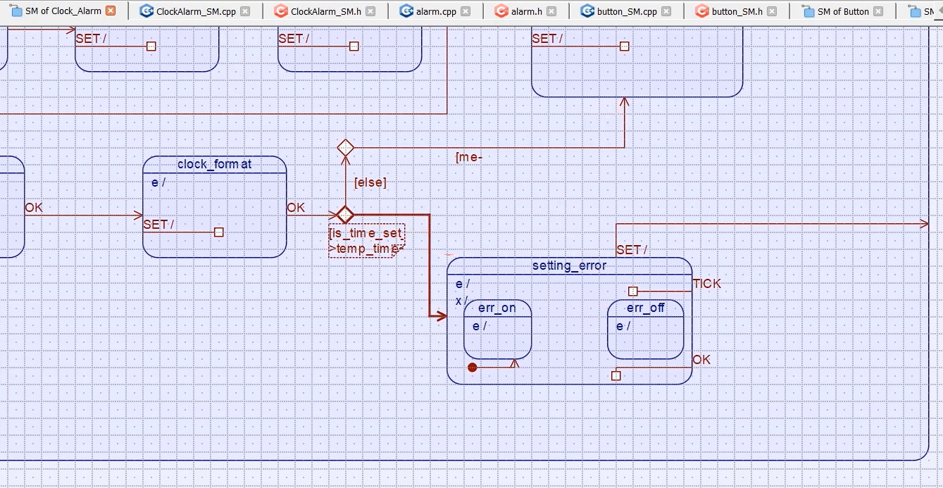
And also, in the Alarm_Notify state, I have not implemented these links between these substates. We will do that now.
When we are in an error state, we flash an error message for every 500 milliseconds. How do we implement that? We implemented that using variables. So, we used one timeout variable, and we incremented that timeout variable whenever the tick signal was received and then compared it with some timeout value like that.
Now, you can get rid of all those things. You can use the timeout function provided by the framework.
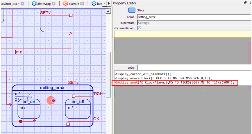
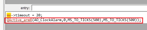
When we enter the setting_error state, let’s arm for a periodic timeout, as an entry action of this state. Let’s go to the entry action and arm a timeout.
QActive_armX() function, as shown in Figure 3.
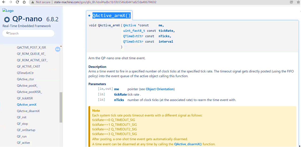
Let’s use QActive_armX(). Here Active object is AO_ClockAlarm. After that, the Tick rate is 0. The number of ticks is 500 ticks or 500 milliseconds. So, you can use MS_TO_TICKS here. In this case, 500 ticks are the same as 500 ms, because our frequency is 1000Hz. And after that, the periodicity you have to mention ‘interval’, that is also 500 milliseconds. setting_error states entry action code is shown in Figure 4.
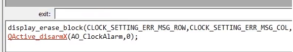
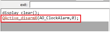
Whenever this setting_error state is exited, you have to disarm that. QActive_disarmX() function is shown in Figure 5.
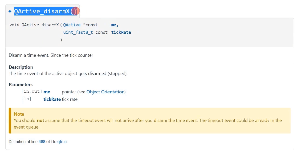
Put QActive_disarmX() as an exit action. You have to mention the Pointer to the AO and the tick rate 0.
Whenever there is a timeout, the state machine receives Q_TIME. That’s why we will transit like this. The signal name is Q_TIMEOUT. This is shown in Figure 7.
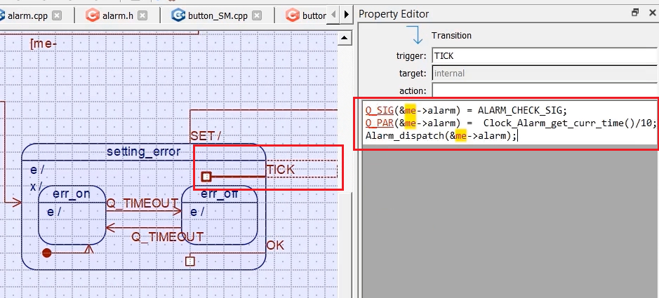
Whenever a tick happens here, then you have to inform the alarm class about the current time. The tick transition code is shown in Figure 8.
Now, go to the Alarm_notify state. Here, I have used one timeout variable. I’ll tell you why that is required. In the entry action of this alarm notify, you have to arm the timer. Let’s take the same code of setting_error state entry and exit actions. Let’s put in the entry action of this one.
In the exit action, the disarm function.
And let’s draw one transition, and I’ll use one choice node here. The signal name is Q_TIMEOUT.
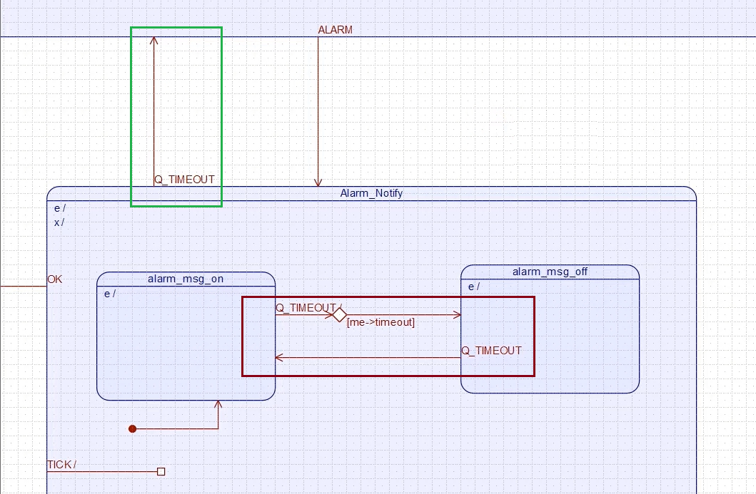
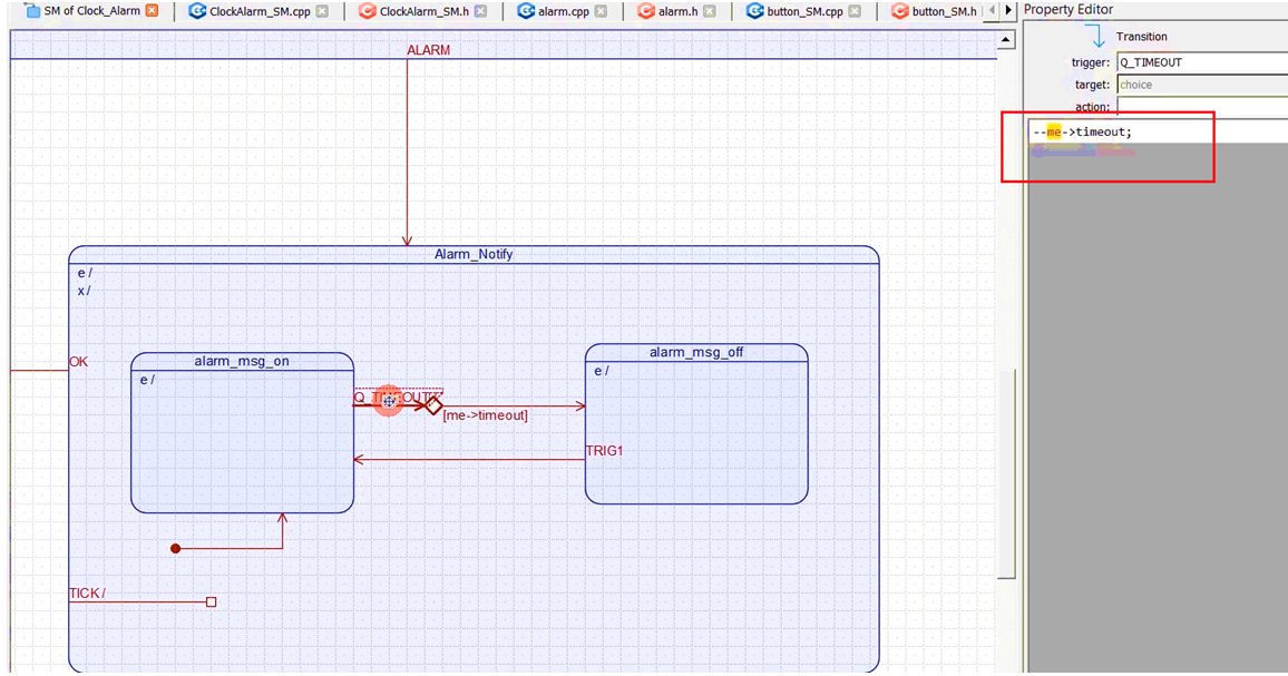
Whenever Q_TIMEOUT happens, what I do is I decrement a timeout variable –-me->timeout; And, in the guard condition of this choice segment, I’ll put one guard condition, that is me->timeout.
Whenever a timeout signal is received, the timeout variable is decremented by one, and then it will be compared. If it is non-zero, that will transition to this alarm_msg_off state. And, whenever the state machine is in this state, this trigger name is again Q_Timeout.
After some time, if no one presses this OK button, then after 20 seconds, this timeout variable will be 0. So, this guard fails. When this fails, this Q_Timeout signal will propagate to the superstate, and we will transition from the Alarm_notify state to the Settings state.
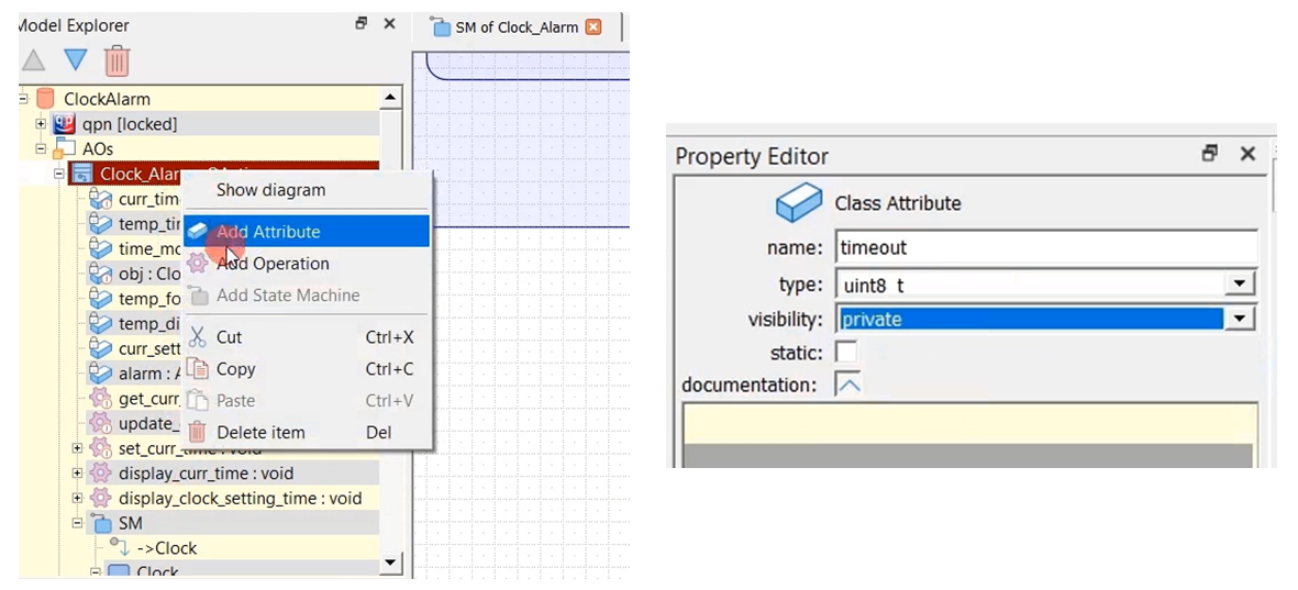
The initial state is the Ticking state. It enters into a ticking state. Let me create that variable timeout in the clock alarm. I think that variable is not there. Let me create it.
Right-click on Clock_Alarm, select Add attribute. Name it as timeout; type is uint8_t; visibility is private, as shown in Figure 13.
Let’s generate the code. The code has generated successfully. And, let’s go back to the IDE. Let’s try to compile this. There are already some errors. So, let’s see.
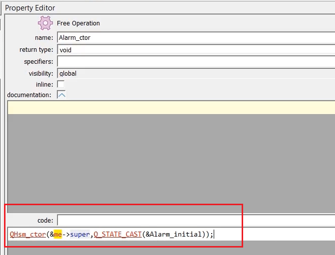
First of all, let’s start from the alarm.cpp. Go here Alarm_ctor, and it says some problems here.
void Alarm_ctor(Alarm *const me) {
    QHsm_ctor(me,Q_STATE_CAST(&Alarm_initial));
}
Let’s copy this ${AOs::Alarm_ctor). Let’s go to the model and paste the link. It takes you to that code.
The code is actually &me->super.
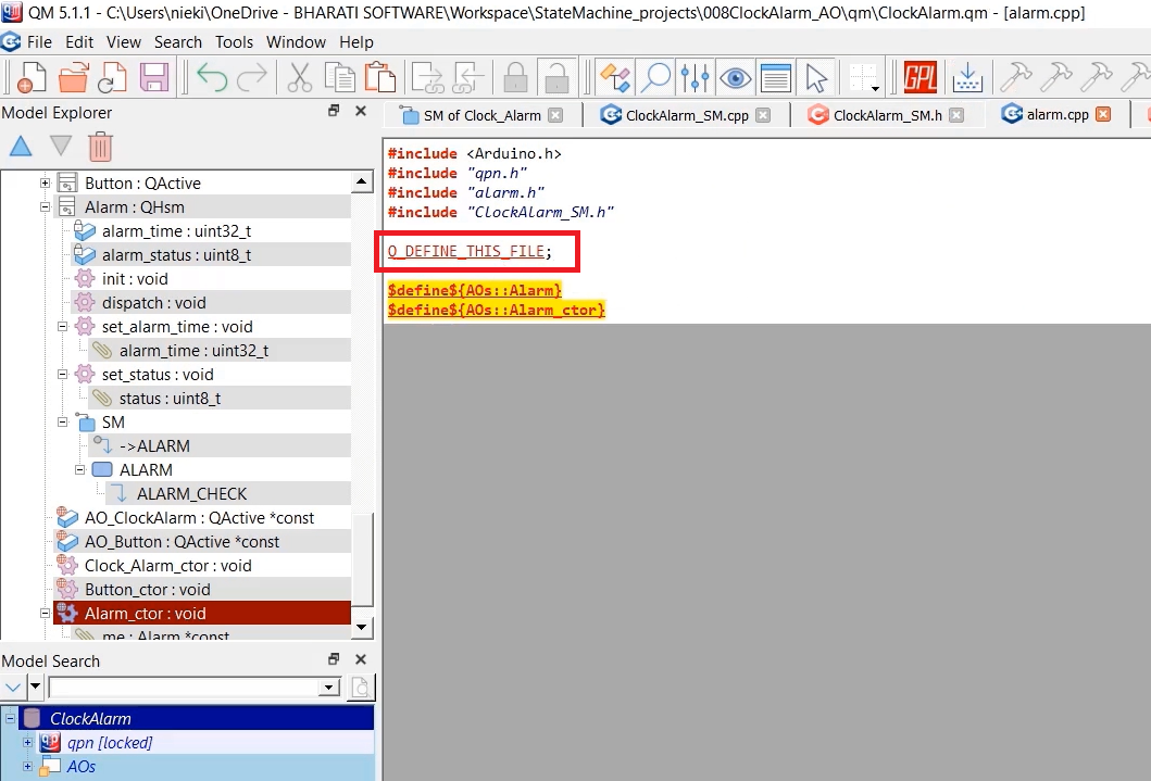
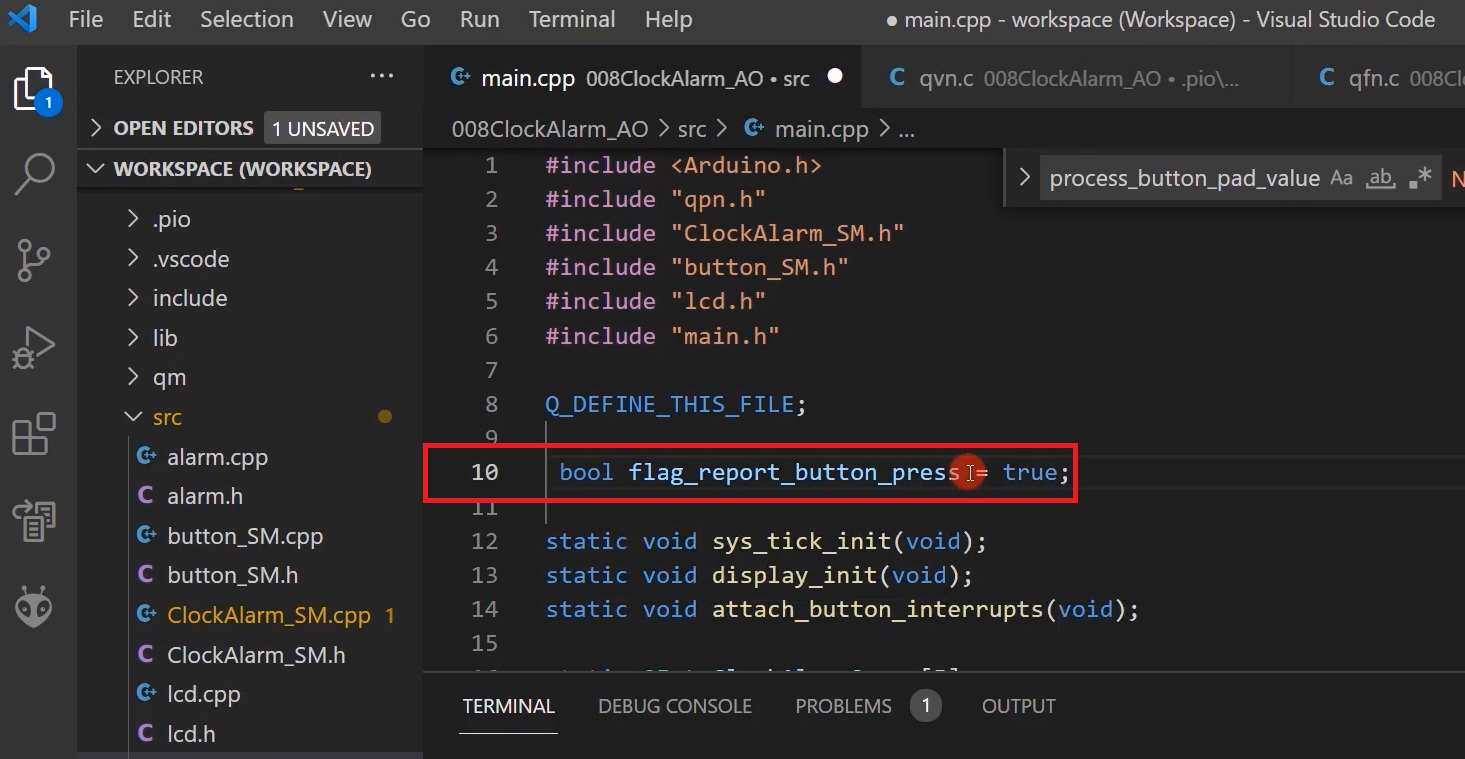
Now, let’s go to the next one. Identifier this module is undefined. Go to the model and go to alarm.cpp, here define this macro→ Q_DEFINE_THIS_FILE.(shown in Figure 15)
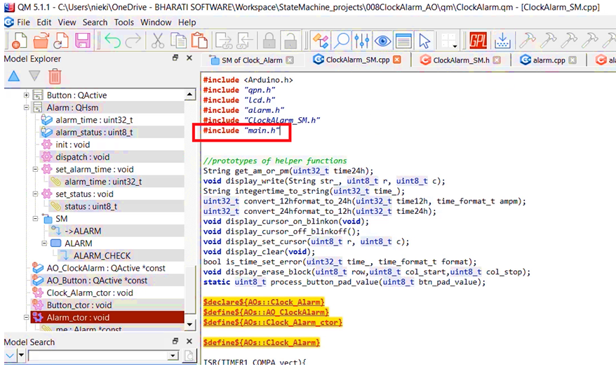
There are a couple of errors in the ClockAlarm_SM.cpp. These macros are not available here.
static QState Clock_Alarm_Alarm_Notify(Clock_Alarm * const me) {
      QState status_;
      switch (Q_SIG(me)) {
           /*.${AOs::Clock_Alarm::SM::Alarm_Notify} */
            case Q_ENTRY_SIG: {
                   me->timeout = 20;
                   QActive_armX(AO_ClockAlarm,0,MS_TO_TICKS(500),MS_TO_TICKS(500));
                   status_ = Q_HANDLED();
                   break;
            }
Go to the ClockAlarm_SM.cpp and include the main.h(shown in Figure 16).
After that, there is one more error. We used the Alarm_get_alarm_time method, but we didn’t give that method. We will do that.
Let’s go back to the model, Go to the Alarm, add one more operation called get_alarm_time. The return type is uint32_t, which is a public function. And the code is return me->alarm_time.
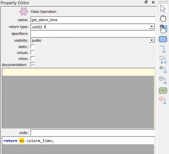
In the main.cpp give the definition of that, as shown in figure 18.
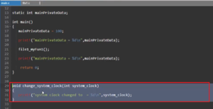
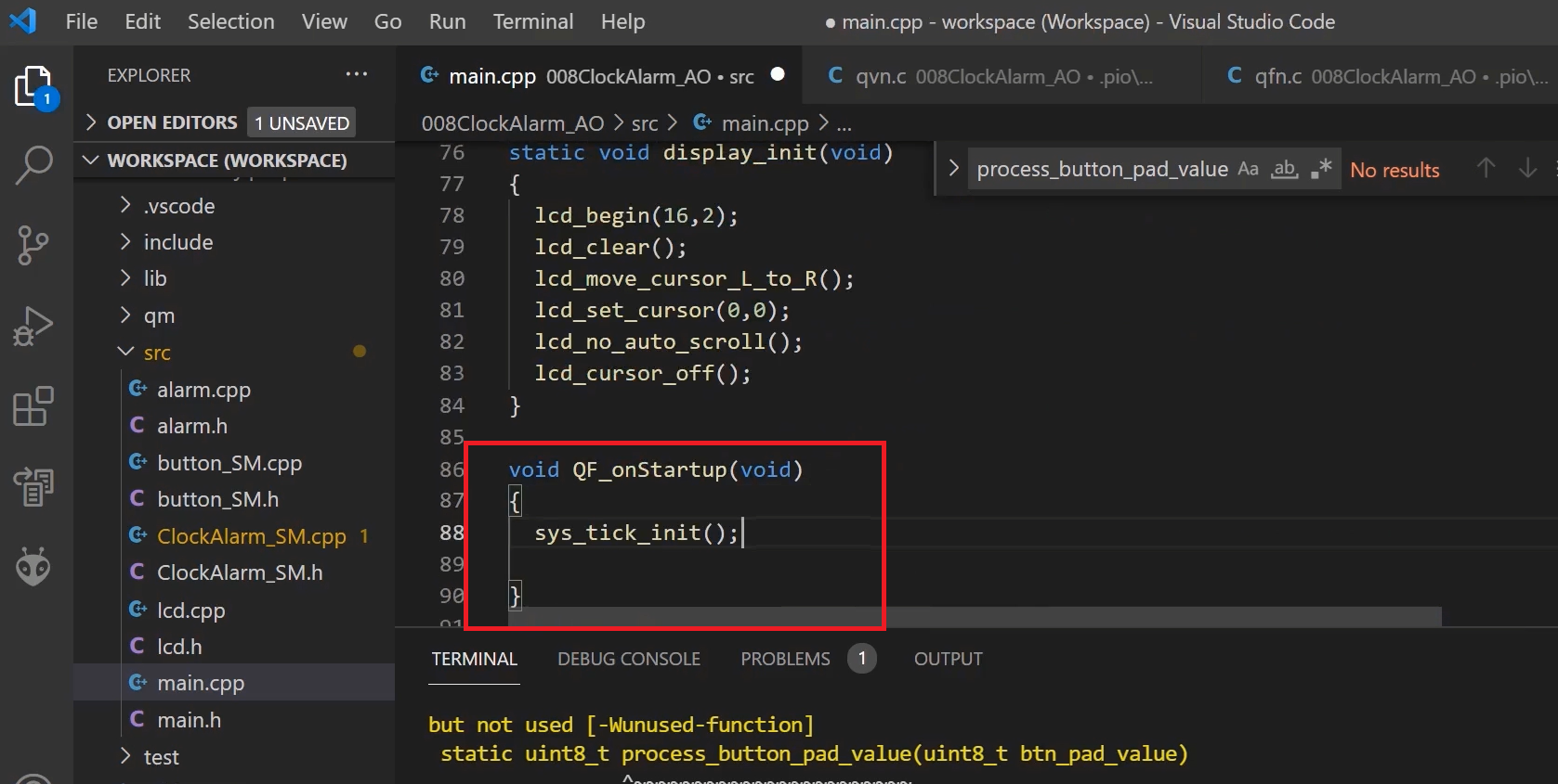
When you start the QF_run here, QF_run runs, and it calls a hook function called startup. It is a startup call back to the application. We will implement this function in our main.cpp.
Let’s go to the main.cpp, let’s implement. QF_onStartup. And from here, we will call that function sys_tick_init().
FastBit Embedded Brain Academy Courses,
Click here: https://fastbitlab.com/course1