GPIO output mode with open drain state

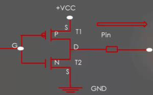
Open-drain output configuration is nothing but the top PMOS transistor is deactivated as shown in Figure1.
When the transistor is ON, the pin pulled to the ground. When the transistor is OFF, the drain of the transistor will be floating or open. That’s the reason it is called an open drain.
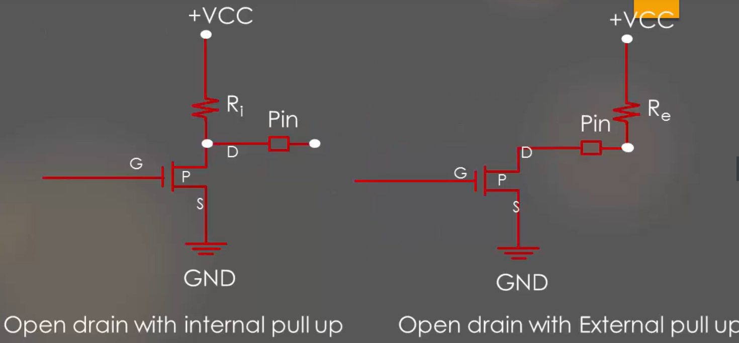
So, an open-drain configuration can only pull-down the pin, but it lacks pulling up capability. Open-drain configuration has two states, either ground or floats. Both are useless until you introducing pull-up resistor by either activating internal pull-up or external pull-down resistor as shown in Figure2.

To achieve a logically high output on the pin, a pull-up resistor connected to the open-drain output to the desired output voltage level. Most applications that utilize open-drain circuitry utilize external pull-ups on open-drain outputs. Often, internal pull-up values are not sufficient for the target circuitry.
In the following article, let’s learn GPIO output mode with push pull state.
FastBit Embedded Brain Academy Courses,
Click here: https://fastbitlab.com/course1


