I2C rise time calculation
The TRISE timing for the I2C communication must be configured in the I2C driver by programming the TRISE register of the I2C register shown in Figure 1.
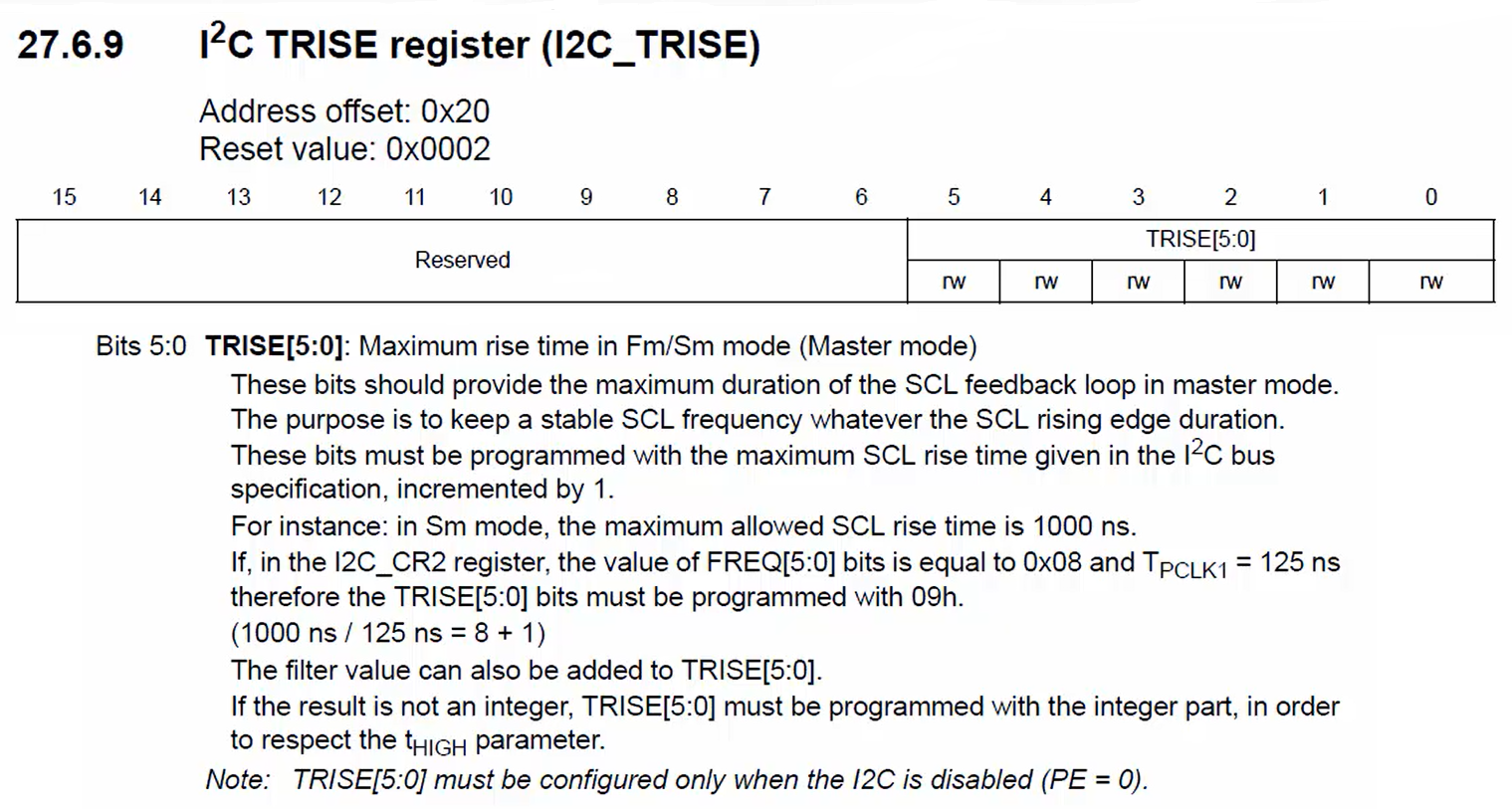
Now let’s include the TRISE calculation in I2C init. Refer to the TRISE register in Figure 1. Here only 5-bits are valid.
The TRISE mentions the maximum rise time in Fm/Sm mode (Master mode). The maximum rise time is given in the specification.
These bits must be programmed with the maximum SCL rise time given in the I2C bus specification, incremented by 1.
For example, consider the standard mode. The maximum allowed SCL rise time for standard mode is 1000 nanoseconds. If in the I2C_CR2 register, the value of the FREQ field is 0x08, which means the AHB1 clock or PCLK1 is 8MHz and TPCLK1=125ns. Add 1 to the result got by dividing the rise time by the time period of the PCLK1 and store it in the TRISE field.
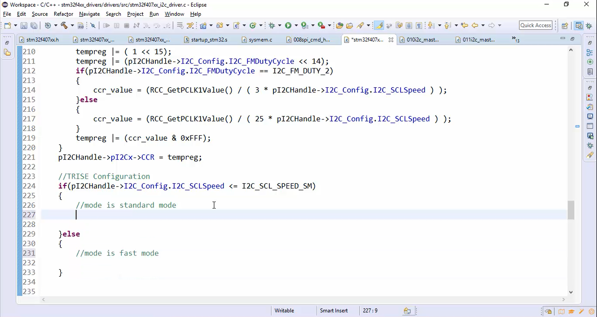
In the I2C init, do the TRISE configuration as follows:
- Check whether the mode is a standard mode or a fast mode (Figure 2).
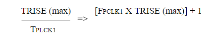
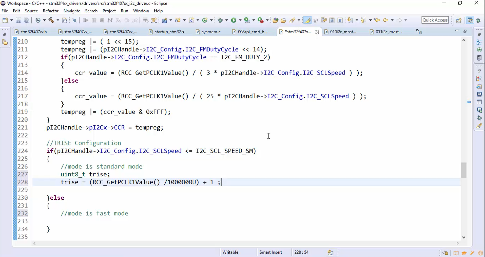
If the mode is the standard mode, TRISE is obtained by multiplying PCLK1 obtained from RCC with the maximum TRISE in the standard mode that is 1000ns. 1000ns is equal to 1 microsecond. Then the multiplied value is divided by 1MHz and add 1 to the result according to the reference manual.
The TRISE calculation for the standard mode is as shown in Figure 3.
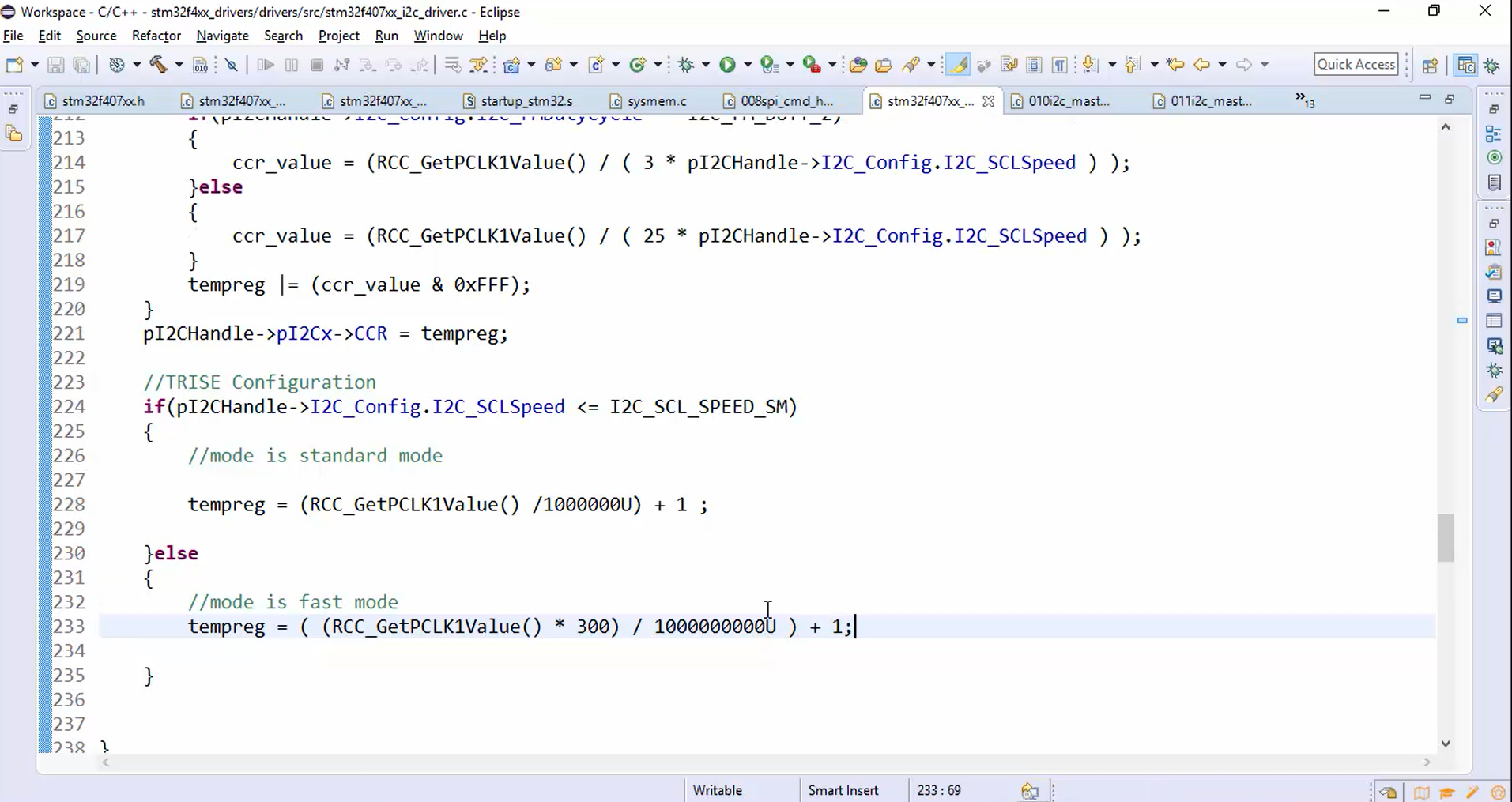
If the mode is the fast mode, TIRSE is obtained by multiplying PCLK1 obtained from RCC with the maximum TRISE in the standard mode that is 300ns. Then the multiplied value is divided by 1MHz and add 1 to the result.
The TRISE calculation for the fast mode is as shown in Figure 4.
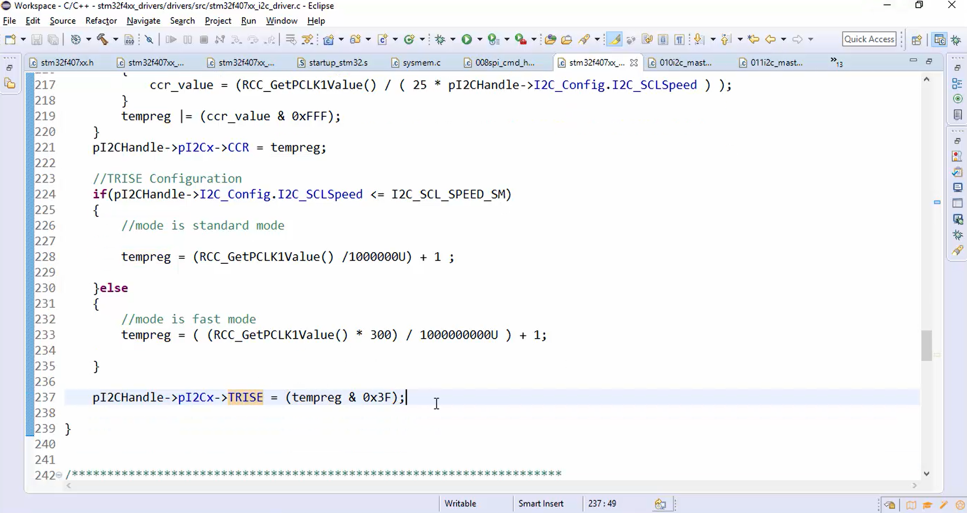
- After calculating the TRISE value, program the TRISE (Figure 5). In TRISE, only 5-bits are valid, so mask all the values of tempreg except the first 5-bits of TRISE register and store that value into the TRISE register, as shown in Figure 5.
FastBit Embedded Brain Academy Courses
Click here: https://fastbitlab.com/course1