LTDC layer testing on hardware
The term “LTDC layer” typically refers to the Layered Timing Controller (LTDC) in embedded systems, particularly in microcontrollers and display driver circuits. LTDC is responsible for managing the timing and control signals for driving an LCD (Liquid Crystal Display) or TFT (Thin-Film Transistor) display.
The LTDC layer acts as an interface between the microcontroller and the display panel. It receives pixel data from the microcontroller and converts it into the necessary control signals for the display. These control signals include horizontal and vertical synchronization signals, pixel clocks, data enable signals, and control signals for backlight control, if applicable.
The LTDC layer typically provides features such as resolution scaling, pixel formatting, color space conversion, and blending of multiple layers. It allows the microcontroller to control the display parameters, such as refresh rate, color depth, and display orientation.
By utilizing the LTDC layer, developers can efficiently drive and control displays in embedded systems, providing graphical user interfaces, animations, and other visual content. The layer facilitates the seamless integration of displays into various applications, including automotive dashboards, medical devices, industrial control systems, and more.
Now, we will set a background color for our frame buffer. The frame buffer is located in the bsp_lcd_ex.c file and its size is determined by FB_SIZE. So, based on the pixel format you have chosen in the bsp_lcd.h.
uint8_t bsp_fb[FB_SIZE];
#include "bsp_lcd.h"

#if BSP_LCD_PIXEL_FMT == BSP_LCD_PIXEL_FMT_RGB565
   #define FB_SIZE (BSP_FB_WIDTH * BSP_FB_HEIGHT * 2)
#elif BSP_LCD_PIXEL_FMT == BSP_LCD_PIXEL_FMT_RGB666
   #define FB_SIZE ((BSP_FB_WIDTH * BSP_FB_HEIGHT * 2) + ((BSP_FB_WIDTH * BSP_FB_HEIGHT *2)/8U)+1U)
#elif BSP_LCD_PIXEL_FMT == BSP_LCD_PIXEL_FMT_RGB888
   #define FB_SIZE (BSP_FB_WIDTH * BSP_FB_HEIGHT * 3)
#else
    #error"Select pixel format"
#endif

uint8_t bsp_fb[FB_SIZE];
Set the background color:
The background color is usually defined in the frame buffer as a pixel value. Each pixel is represented by a certain number of bits, where each bit determines the color of a specific component (e.g., red, green, blue, and alpha). The number of bits per component and the organization of the frame buffer depend on your display configuration and pixel format.
Look at below, which displays a function called set_fb_background_color. To utilize this function, you need to provide an RGB888 value as input. The function internally performs a conversion to RGB565 based on the pixel format. Currently, only this particular conversion is supported. However, you have the option to implement additional conversions if needed. To set the desired color, simply invoke this function with the appropriate color parameter.
void bsp_lcd_set_fb_background_color(uint32_t rgb888)
{
#if(BSP_LCD_PIXEL_FMT == BSP_LCD_PIXEL_FMT_RGB565)
     write_to_fb_rgb565((uint16_t*)bsp_fb,(FB_SIZE/2U),Convert_RGB888_to_RGB565(rgb888));
#elif(BSP_LCD_PIXEL_FMT == BSP_LCD_PIXEL_FMT_RGB666)
     write_to_fb_rgb666(Convert_RGB888_to_RGB666(rgb888));
#elif(BSP_LCD_PIXEL_FMT == BSP_LCD_PIXEL_FMT_RGB888)
     write_to_fb_rgb888(rgb888);
#else
         #error"Select pixel format"
#endif
}
void bsp_lcd_set_fb_background_color(uint32_t rgb888)
This is the function declaration for setting the background color of the frame buffer. It takes an input rgb888 which represents the desired color in RGB888 format (8 bits per color channel).
#if(BSP_LCD_PIXEL_FMT == BSP_LCD_PIXEL_FMT_RGB565)
write_to_fb_rgb565((uint16_t*)bsp_fb,(FB_SIZE/2U, Convert_RGB888_to_RGB565(rgb888));
#elif(BSP_LCD_PIXEL_FMT == BSP_LCD_PIXEL_FMT_RGB666)
write_to_fb_rgb666(Convert_RGB888_to_RGB666(rgb888));
#elif(BSP_LCD_PIXEL_FMT == BSP_LCD_PIXEL_FMT_rgb888)
write_to_fb_rgb888(rgb888));
This code snippet uses preprocessor directives (#if, #elif, #else, #endif) to conditionally execute different code based on the selected pixel format (BSP_LCD_PIXEL_FMT). It assumes three possible pixel formats: RGB565, RGB666, and rgb888.
- If the pixel format is RGB565, the function write_to_fb_rgb565 is called with the frame buffer bsp_fb, the size of the frame buffer divided by 2 ((FB_SIZE/2U)), and the converted RGB565 color obtained from Convert_RGB888_to_RGB565(rgb888).
- If the pixel format is RGB666, the function write_to_fb_rgb666 is called with the converted RGB666 color obtained from Convert_RGB888_to_RGB666(rgb888).
- If the pixel format is rgb888, the function write_to_fb_rgb888 is called with the RGB888 color rgb888.
else
#error”Select pixel format”
#endif
If none of the defined pixel formats match the selected format, a preprocessor error directive is triggered, indicating that the pixel format needs to be selected properly.
To set the background color, you would call this function with the desired color represented in RGB888 format. The function will handle the conversion based on the selected pixel format and write the appropriate color value to the frame buffer.
In the file bsp_lcd.h, you provide the prototype of the function bsp_lcd_set_fb_background_color.
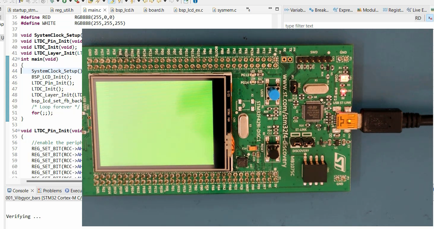
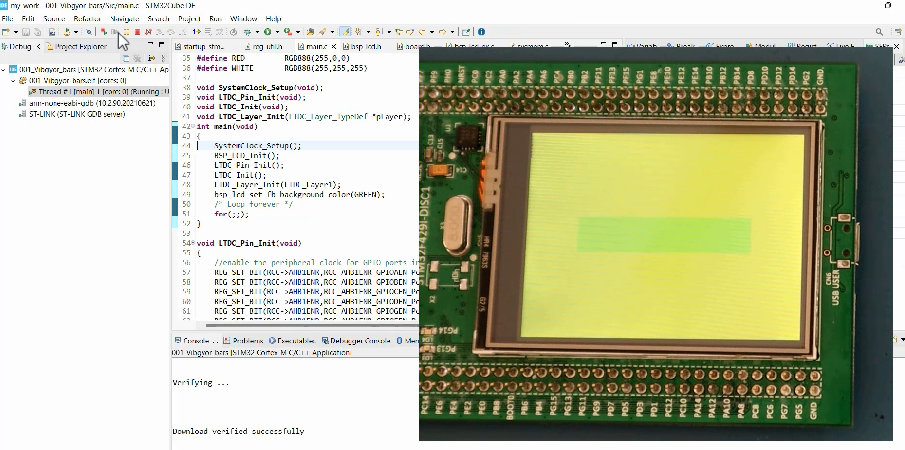
In the main.c file, define hexadecimal values for various colors (as shown below). Then, call the bsp_lcd_set_fb_background_color function using any of those colors. Here, I’ll use the color green. This function sets the color of the layer since the frame buffer address is associated with Layer 1.
#define VIOLET RGB888(148,0,211)
#define INDIGO RGB888(75,0,130)
#define BLUE RGB888(0,0,255)
#define GREEN RGB888(0,255,0)
#define YELLOW RGB888(255,255,0)
#define ORANGE RGB888(255,127,0)
#define RED RGB888(255,0,0)
#define WHITE RGB888(255,255,255)


void SystemClock_Setup(void);
void LTDC_Pin_Init(void);
void LTDC_Init(void);
void LTDC_Layer_Init(LTDC_Layer_TypeDef *pLayer);
int main(void)
{
       SystemClock_Setup();
       BSP_LCD_Init();
       LTDC_Pin_Init();
       LTDC_Init();
       LTDC_Layer_Init(LTDC_Layer1);
       bsp_lcd_set_fb_background_color(GREEN);

/*loop forever*/

for(;;);
After executing the code, you will observe that the display module does display the color green, as shown in Figure 1.
Now, let’s experiment by reducing the layer size. In the “Configure Layer Position” (windowing) step, we will modify the code. Open the main.c file and locate the section for the start calculation. Here, you need to use BSP_LTDC_LAYER_H_START for horizontal start calculation and BSP_LTDC_LAYER_V_START for vertical start calculation.
Similarly, you should use BSP_LTDC_LAYER_WIDTH for horizontal stop calculation. And for the vertical stop calculation, you need to use BSP_LTDC_LAYER_HEIGHT.
//Configure layer position (Windowing)
uint32_t AHBP = REG_READ_VAL(pLTDC->BPCR,0xFFFU,LTDC_BPCR_AHBP_Pos);
uint32_t WHSTART = AHBP+BSP_LTDC_LAYER_H_START +1;
REG_SET_VAL(tmp,WHSTART,0xFFFU,LTDC_LxWHPCR_WHSTPOS_Pos);

uint32_t WHSTOP = AHBP+BSP_LTDC_LAYER_H_START+BSP_LTDC_LAYER_WIDTH+1;
uint32_t AAW = REG_READ_VAL(pLTDC->AWCR,0xFFFU,LTDC_AWCR_AAW_Pos);
WHSTOP = (WHSTOP > AAW)?AAW:WHSTOP;
REG_SET_VAL(tmp,WHSTOP,0xFFFU,LTDC_LxWHPCR_WHSPPOS_Pos);

REG_WRITE(pLayer->WHPCR,tmp);

tmp = 0;
uint32_t AVBP = REG_READ_VAL(pLTDC->BPCR,0x7FFU,LTDC_BPCR_AVBP_Pos);
uint32_t WVSTART = AVBP+BSP_LTDC_LAYER_V_START+1;
REG_SET_VAL(tmp,WVSTART,0x7FFU,LTDC_LxWVPCR_WVSTPOS_Pos);

uint32_t AAH = REG_READ_VAL(pLTDC->AWCR,0x7FFU,LTDC_AWCR_AAH_Pos);
uint32_t WVSTOP = AVBP+BSP_LTDC_LAYER_V_START+BSP_LTDC_LAYER_HEIGHT+1;
WVSTOP = (WVSTOP > AAH)?AAH:WVSTOP;
REG_SET_VAL(tmp,WVSTOP,0x7FFU,LTDC_LxWVPCR_WVSPPOS_Pos);

REG_WRITE(pLayer->WVPCR,tmp);
After executing this code, you will notice that the inactive area of the layer appears black, but you can modify this behavior. This can be achieved by configuring the default color of the layer.
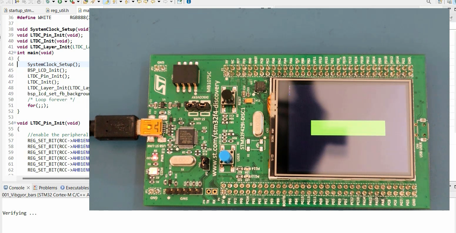
To accomplish this, you need to make changes in the code section titled ‘Configure the default color of the layer.’ This modification will affect the inactive area of the layer. Specifically, you will use the command
REG_WRITE(player->DCCR, YELLOW);
Here the register is DCCR and the value is Yellow.
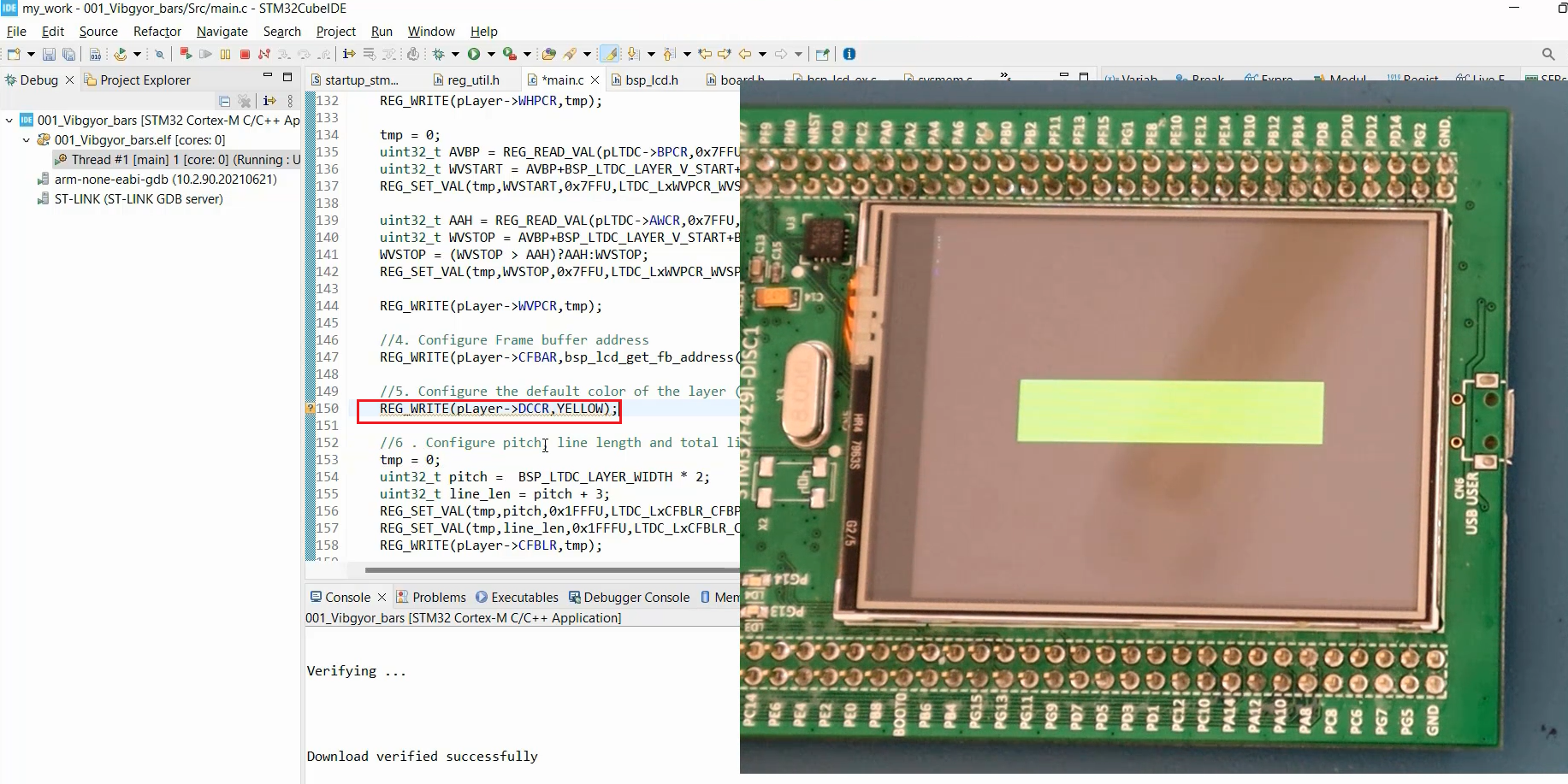
Once the necessary changes have been made, relaunch the program.
As a result, you will observe that the inactive area of the layer now displays the color Yellow, while the active area of the layer continues to utilize the frame buffer values.
In the following article, let’s do our task, which is to show the color bars.
Get the Mastering Microcontroller: STM32-LTDC, LCD-TFT, LVGL(MCU3) Full course on Here.
FastBit Embedded Brain Academy Courses
Click here: https://fastbitlab.com/course1