Bit-field structure for GPIOx_ODR
A GPIOx_ODR (GPIO Output Data Register) is a register used in microcontrollers or systems-on-chip (SoCs) to control the output state of the GPIO (General Purpose Input/Output) pins.
A bit-field structure for the GPIOx_ODR register defines the individual bits within the register and their corresponding functions. The exact structure of the register can vary depending on the specific microcontroller or SoC architecture.
I created typedef structures for the GPIO_ODR register and also for the GPIO_MODE register.
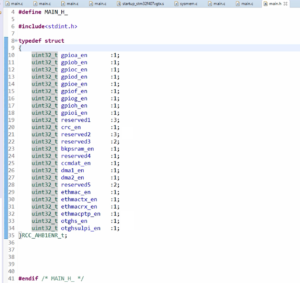
typedef struct
{
    uint32_t pin_0    :1;
    uint32_t pin_1    :1;
    uint32_t pin_2    :1;
    uint32_t pin_3    :1;
    uint32_t pin_4    :1;
    uint32_t pin_5    :1;
    uint32_t pin_6    :1;
    uint32_t pin_7    :1;
    uint32_t pin_8    :1;
    uint32_t pin_9    :1;
    uint32_t pin_10   :1;
    uint32_t pin_11   :1;
    uint32_t pin_12   :1;
    uint32_t pin_13   :1;
    uint32_t pin_14   :1;
    uint32_t pin_15   :1;
    uint32_t reserved :16;
}GPIOx_ODR_t;
typedef struct for the GPIOx_ODR register
In this example, each bit in the register corresponds to a specific GPIO pin, numbered from 0 to 15. The pin_0 bit controls the output state of GPIO Pin 0, Pin_1 bit controls GPIO Pin 1, and so on. The structure also includes reserved bits, which are typically used for alignment or future use.
typedef struct
{
    uint32_t pin_0  :2;
    uint32_t pin_1  :2;
    uint32_t pin_2  :2;
    uint32_t pin_3  :2;
    uint32_t pin_4  :2;
    uint32_t pin_5  :2;
    uint32_t pin_6  :2;
    uint32_t pin_7  :2;
    uint32_t pin_8  :2;
    uint32_t pin_9  :2;
    uint32_t pin_10 :2;
    uint32_t pin_11 :2;
    uint32_t pin_12 :2;
    uint32_t pin_13 :2;
    uint32_t pin_14 :2;
    uint32_t pin_15 :2;
}GPIOx_MODE_t;
typedef struct for the GPIOx_MODE register
Here I used the name GPIOx because the same structure I can use with any GPIO peripheral. It need not be GPIOD, GPIOA, or GPIOB. So, this is a generic structure. Because it can be used with mode to register of any GPIO peripheral.
And pin_0, pin_1, pin_2, pin_15, and so on, these are the member elements. So, here you can even use pin mode 0, or pin mode 1, like that. I just used the names pin_0, and pin_1, like that.
And for the GPIOx_ODR, you can see that(Figure 1) only 15-bit positions are valid and the rest are reserved. So, that’s the reason 16-bit positions are reserved.
In the following article, let’s see what to do with these typedef structures. So, we have learn how to configure the peripheral registers using these typedef structures.
FastBit Embedded Brain Academy Courses
Click here: https://fastbitlab.com/course1