Modifying led toggle exercise with macros
In C, macros are used to define reusable pieces of code or constants that are substituted directly into the code during preprocessing. Macros are preprocessor directives and are typically defined using the #define directive.
In this article, we will enhance our previous program, led_toggle_bitfields, by incorporating macros to make the code more organized and readable. Macros are a powerful tool for simplifying code and abstracting away complex values or addresses.
Let’s modify the below code and let’s see where and all we can make use of macros here.
#include "main.h"

int main(void)
{
   RCC_AHB1ENR_t volatile *const pClkCtrlReg = (RCC_AHB1ENR_t*) 0x40023830;
   GPIOx_MODE_t volatile *const pPortDModeReg = (GPIOx_MODE_t*) 0x40020C00;
   GPIOx_ODR_t volatile *const pPortDOutReg = (GPIOx_ODR_t*) 0x40020C14;

   //1. enable the clock for GPOID peripheral in the AHB1ENR (SET the 3rd bit position)
   pClkCtrlReg->gpiod_en = 1;

   //2. configure the mode of the IO pin as output
   pPortDModeReg->pin_12 = 1;

   while(1)
   {
      //Set 12th bit of the output data register to make I/O pin-12 as HIGH
      pPortDOutReg->pin_12 = 1;

      //introduce small human observable delay
     //This loop executes for 300K times
     for(uint32_t i=0 ; i < 300000 ; i++ );

     //Reset 12th bit of the output data register to make I/O pin-12 as LOW
     pPortDOutReg->pin_12 = 0;

    for(uint32_t i=0 ; i < 300000 ; i++ );
   }

   for(;;);
}
led_toggle_bitfields program code
Define a Macro:
To define a macro, use the #define directive followed by the macro name and its replacement value.
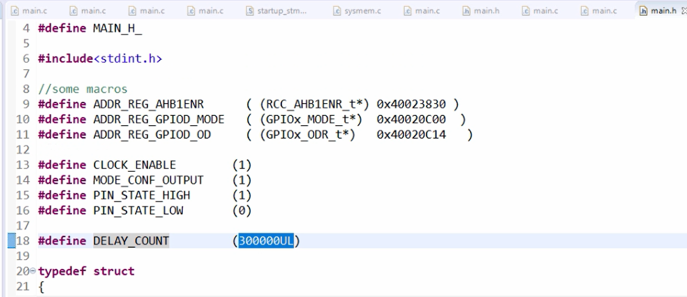
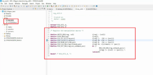
The defined macros are shown in Figure 1 and the Modified code is below code snippet.
Here, there is an address represented as (RCC_AHB1ENR_t*) 0x40023830. To hide this number, a macro can be used. This can be achieved by creating macros in main.h.
The number 0x40023830 is the register address of the AHB1_ENR register. A macro named ADDR_REG_AHB1ENR can be created with the value ((RCC_AHB1ENR_t*) 0x40023830) to represent this address.
#define ADDR_REG_AHB1ENR ( (RCC_AHB1ENR_t*) 0x40023830)
Similar to ADDR_REG_AHB1ENR, two more macros can be created for GPIOD_MODE and GPIOD_OD, named ADDR_REG_GPIOD_MODE and ADDR_REG_GPIOD_OD respectively with their corresponding values.
#define ADDR_REG_GPIOD_MODE ( (GPIOx_MODE_t*) 0x40020C00)
#define ADDR_REG_GPIOD_OD ( (GPIOx_ODR_t*) 0x40020C14)
According to our guideline for writing macros, a macro value must be inside parentheses. That’s why let’s use the parentheses here.

#include "main.h"

int main(void)
{
   RCC_AHB1ENR_t volatile *const pClkCtrlReg   = ADDR_REG_AHB1ENR;;
   GPIOx_MODE_t  volatile *const pPortDModeReg = ADDR_REG_GPIOD_MODE;
   GPIOx_ODR_t   volatile *const pPortDOutReg  = ADDR_REG_GPIOD_OD;

   //1. enable the clock for GPOID peripheral in the AHB1ENR (SET the 3rd bit position)
   pClkCtrlReg->gpiod_en = CLOCK_ENABLE;

   //2. configure the mode of the IO pin as output
   pPortDModeReg->pin_12 = MODE_CONF_OUTPUT;

  while(1)
  {
  //Set 12th bit of the output data register to make I/O pin-12 as HIGH
  pPortDOutReg->pin_12 = PIN_STATE_HIGH;

  //introduce small human observable delay
  //This loop executes for 300K times
  for(uint32_t i=0 ; i < DELAY_COUNT ; i++ );

  //Reset 12th bit of the output data register to make I/O pin-12 as LOW
  pPortDOutReg->pin_12 = PIN_STATE_LOW;

  for(uint32_t i=0 ; i < DELAY_COUNT ; i++ );
  }

 for(;;);
}
Modified code in main.c
1. Enable the clock for the GPIOD peripheral in the AHB1ENR(SET the 3rd-bit position)
pClkCtrlReg-> gpiod_en = 1;
Here, 1 means enable. We can create a meaningful macro named CLOCK_ENABLE for 1.
pClkCtrlReg -> gpiod_en = CLOCK_ENABLE;
And define it as #define CLOCK_ENABLE (1);
When someone sees this code, then it is very clear to them that you are doing some ClOCK_ENABLE thing here.
2. Configure the mode of the IO pin as output
Similarly, we can create a macro named MODE_CONF_OUTPUT for configuring the mode of the IO pin as output
pPortDMODEReg -> pin_12 = MODE_CONF_OUTPUT;
And define it as #define MODE_CONF_OUTPUT (1)
- Set 12th bit of the output data register to make I/O pin-12 as HIGH.
We can create a macro named PIN_STATE_HIGH and define it as #define PIN_STATE_HIGH (1).
- 12th bit of the output data register to make I/O pin-12 as LOW
we can create a macro named PIN_STATE_LOW and define it as #define PIN_STATE_LOW (0).
For the number 300000, we can create a macro named DELAY_COUNT and define it as #define DELAY_COUNT (300000UL). By adding ‘u’ and ‘l’ characters along with the number, we are telling the compiler to treat this number as an unsigned long integer.
Please note that according to our macro writing guidelines, all the things should be in parentheses. That is always better practice.
Now someone can easily understand what’s going on here. Still, you can use more macros to make it more readable.
FastBit Embedded Brain Academy Courses
Click here: https://fastbitlab.com/course1


