I2C Serial clock settings with Explanations
In this article, let’s discuss the various settings that should be done to get the desired serial clock out of the I2C peripheral.
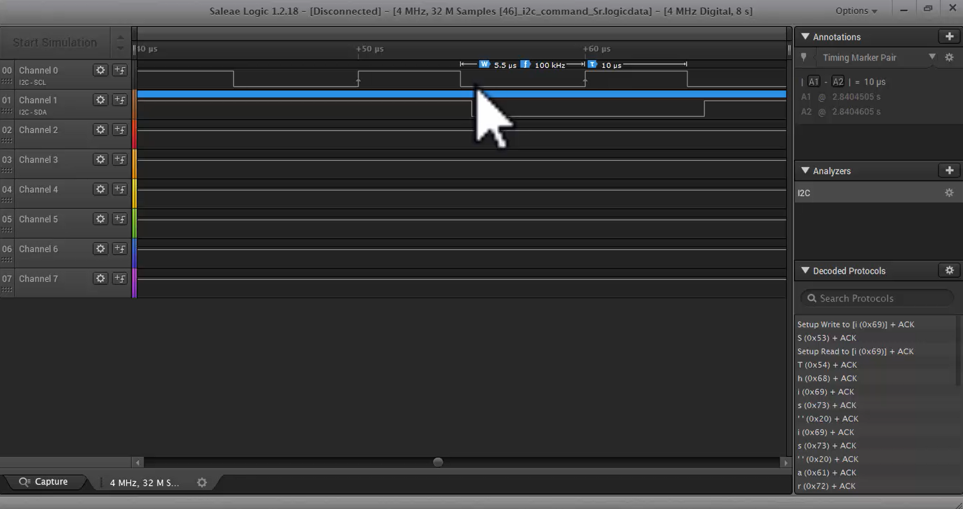
Observe the first line of the I2C old trace shown in Figure 1. Here the first line is a serial clock, and it is the standard mode with around 100kHz.
The CR2 and CCR registers must be configured to get the desired clock in the stm32f4x I2C peripheral. CR2 and CCR registers are used to control the I2C serial clock settings and other I2C timings like setup time and hold time.
In the I2C_CR2 register, look into the FREQ field or frequency field shown in Figure 2. It stores the information about the APB bus to which the I2C peripheral is connected. That means the value of the APB bus clock of the microcontroller is written in this field.

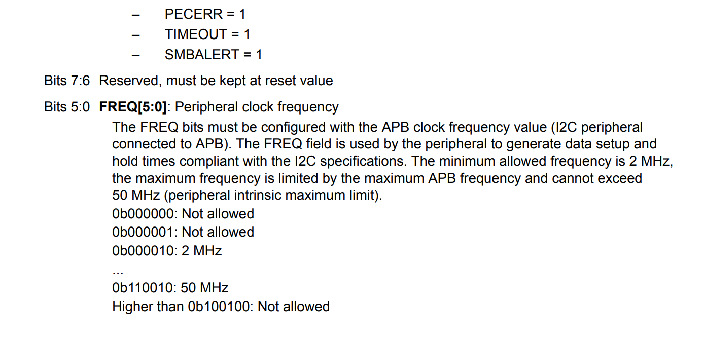
Look at the FREQ field of the CR2 register in Figure 3. It says that peripheral clock frequency.
The FREQ bit must be configured with a clock frequency of the APB bus where the I2C peripheral is connected. This field is initialized by using one of the values among 0b000010 to 0b110010.
I2C hardware uses FREQ information to derive its various I2C related timing details according to the specification. So, configuring this field is very important. Just write the value of the APB clock frequency to this field.
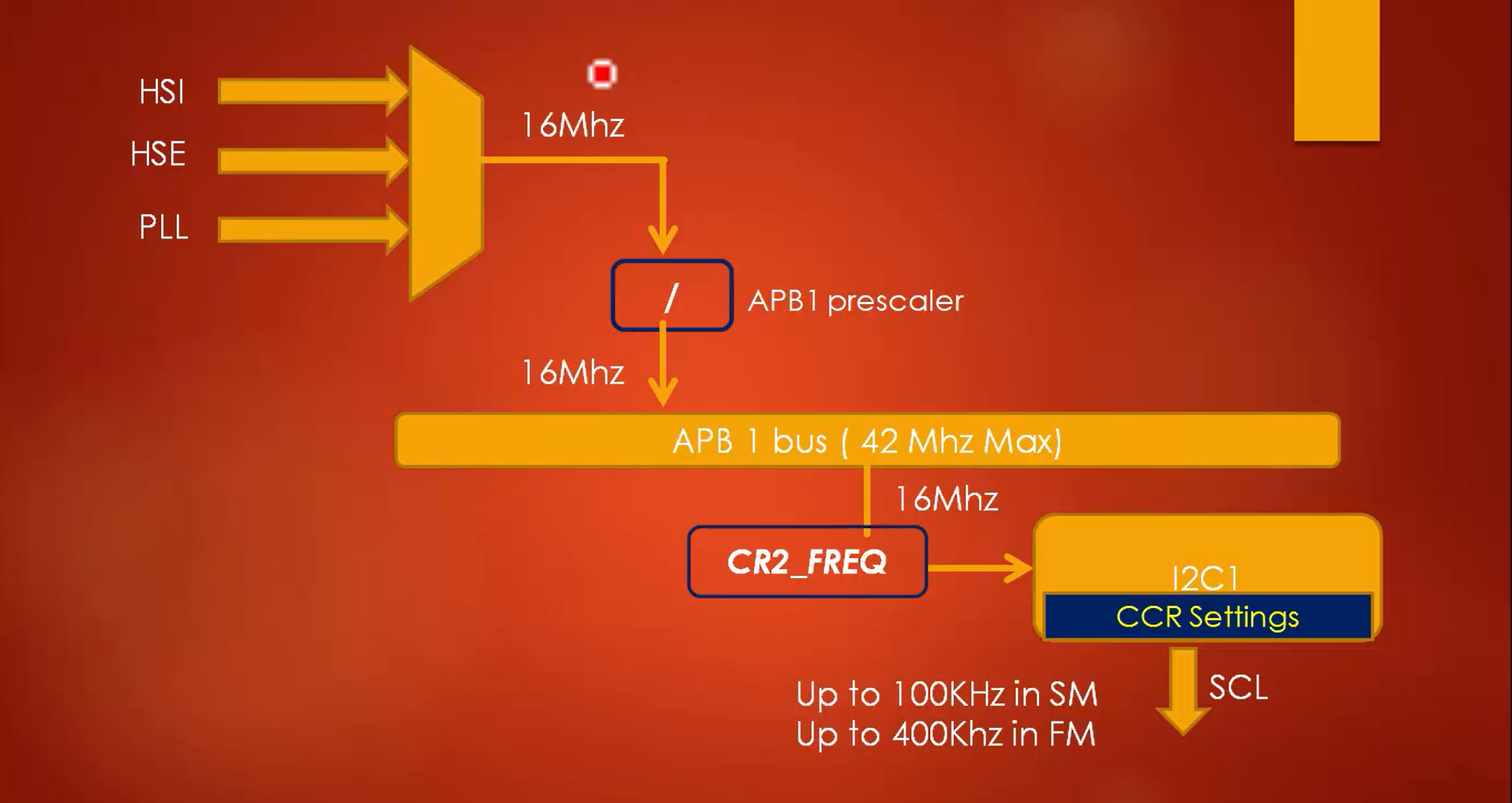
For example, The internal HSI with 16MHz is used if the I2C peripherals are connected to the APB1 bus. Therefore, the APB1 will be 16MHz. Now load the CR2_FREQ with value 16, and this information will be used by the I2C peripheral, and then with the help of CRC settings, it can produce different frequencies of the serial clock, as shown in Figure 4.
Next, configure the CCR field of the I2C_CCR register.
Now, let’s understand the things that have to be done in the CCR field if the application demands to run in standard mode with a serial clock of 100kHz and APB1 clock (PCLK1) 16MHz.
A couple of steps should be followed to generate the 100kHz of the serial clock in this case.
- Configure the mode in CCR register: Select the I2C mode in the 15th-bit position of the CCR register. The mode can be either standard mode or fast mode. In this example, it is the standard mode.
- Program FREQ field of CR2 with the value of PCLK1: The value of PCLK1 is given, which is 16MHz. Now, program the value 16 into the FREQ field of the CR2 register shown in Figure 2.
- Calculate and program CCR value in CCR field of CCR register: There is a CCR field in the CCR register, as shown in Figure 5. The steps for calculating the CCR value is given in the reference manual. Since the application demands to run in standard mode, the formula is as shown in Figure 6.


Now let’s calculate the CCR. The application requires a serial clock of 100kHz, which means the period of the clock will be 10 microseconds. If you consider the duty cycle of 50%, Thigh will be 5 microseconds, and Tlow will be 5 microseconds. Substitute these values in the first formula of Figure 6.
5 x 10 -6 = CCR x Time period of the APB1 clock
The time period of the APB1 clock is 16MHz. When you convert it to time, it will be 62.5 x 10 -9.
5 x 10 -6 = CCR x 62.5 x 10 -9
CCR = (5 / 62.5) x 1000
= 80 (or 0x50 hex)
So, program value 80 into the CCR field of the CCR register. Therefore, to generate the serial clock of 100kHz, configure 16 in the FREQ field and 80 in the CCR field.
Now, let’s see another example for fast mode. In FM mode, generate an SCL frequency of 200kHz and APB1 clock (PCLK1) is 16MHz.
1.Configure the mode in CCR register: Select the I2C mode in the 15th-bit position of the CCR register. The mode can be either standard mode or fast mode. In this example, it is the standard mode.
2. Select the duty cycle of fast mode SCL in CCR register: While working in the fast mode, it is necessary to configure the duty cycle of the serial clock. When the mode is the fast mode, there are two possible duty cycles, as shown in Figure 7.
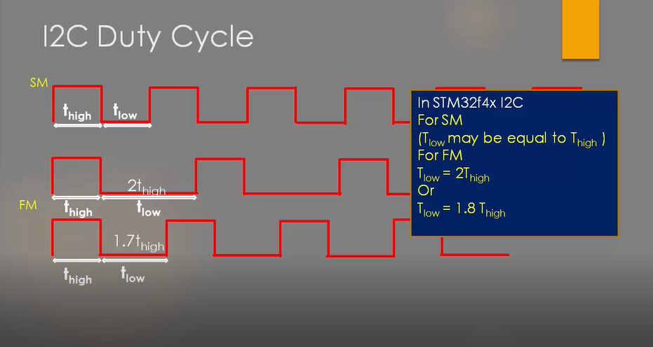
In STM32f4x I2C peripheral, in standard mode, Tlow may be equal to Thigh, which means the duty cycle will be 50%.
But in the fast mode, there are two options (Figure 7). In option 1, Tlow will be twice the Thigh, and in option 2, Tlow is 1.8 times the Thigh. So, in the fast mode, one among these two duty cycles is selected.
There are recommended values for Thigh and Tlow of the serial clock in the specification document, as shown in Figure 8.

Here Tlow means the low period of the serial clock, and Thigh is the high period of the serial clock.
In the standard communication mode, the minimum requirement for the Tlow is 4.7 microseconds, and for Thigh, it is 4 microseconds. In the fast mode, the minimum requirement for the Tlow is 1.3 microseconds, and for Thigh, it is 0.6 microseconds.
For example, if you are using standard mode with a 50% duty cycle at 100kHz, both Tlow and Thigh will be 5 microseconds and indeed meet the standard mode’s minimum requirement.
In the CCR register, the 14th bit is a duty (Figure 9), used to configure the duty cycle. Remember that when the mode is the fast mode, if duty = 0, then the Tlow will be twice the Thigh, and if duty = 1, then the maximum serial clock speed in the fast mode is 400kHz (Figure 9). So, the duty must be 1 to achieve the maximum serial clock speed of 400kHz, which means Tlow is approximately equal to 1.8 times the Thigh.

3. Program FREQ field of CR2 with the value of PCLK1: The value of PCLK1 is given, which is 16MHz. Now, program the value 16 into the FREQ field of the CR2 register.
4. Calculate and program CCR value in CCR field of CCR register: The steps for calculating the CCR value is given in the reference manual. Since the application is in fast mode, the formula is as shown in Figure 10.

Add the Thigh and Tlow equations for Duty = 0
Thigh + Tlow = 3 x CCR x TPCLK1
(5 x 10 -6) / (3 x 62.5 x 10 -9) = CCR
CCR = 26
So, program the value 26 to the CCR register.
If Duty = 1, then the divider factor will be 25 instead of 3.
This is about the serial clock settings. These are all the settings you have to remember in order to produce different values of the serial clock.
In the following article, let’s see Clock Stretching.
FastBit Embedded Brain Academy Courses,
Click here: https://fastbitlab.com/course1

