I2C IRQ and interrupt discussion
In this article, let’s discuss the I2C interrupts and try to develop the non-blocking flavors of the APIs (MasterReceiveData and MasterSendData) discussed in the I2C transactions.
Now let’s understand the IRQ numbers of the I2C and how exactly the I2C peripheral interrupts the processor.
Remember that in all the cases shown in Figure 1, the I2C peripheral can interrupt the processor.
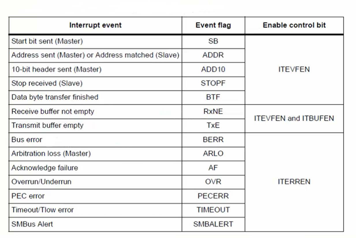
You are already familiar with some of the flags in Figure 1 that may be a start bit indication, address sent flag (or ADDR), stop flag, TXE flag, and BTF, etc. There are lots of errors that may occur during the I2C communication, as shown in Figure 1.
They are bus error, arbitration loss, acknowledgement failure, overrun or underrun, PEC error that is nothing but a mismatch of the CRC if the CRC feature is used, a timeout, etc. All these events have the capacity to interrupt the processor.
Whenever these events (events in Figure 1) happen, the corresponding flag in the status register will be set. Setting up those flags can interrupt the processor only if the control bit corresponding to that flag is enabled. Otherwise, it will not cause any interruption to the processor. Therefore, the control bits in Figure 1 are given to achieve the interruption.
In the polling mode APIs, these control bits are not enabled since the APIs are polling based. Instead, we polled for the flags and then took the decision depending upon the status of the flags.
Note:
- Remember that if you want interrupt for SB, ADDR, ADD10, STOPF, and BTF events, then the control bit ITEVFEN must be enabled in the control register.
- If you want interrupt for Receive buffer not empty and transmit buffer empty events, then the control bits ITEVFEN and ITBUFEN must be enabled in the control register.
- If you want interrupt for any of the error events shown in Figure 1, then the control bit ITERREN must be enabled in the control register.
Now let’s understand how the I2C peripheral interrupts the processor. Figure 2 shows the interrupt mapping diagram of the I2C peripheral.

Let’s assume the I2C peripheral in Figure 2 as the I2C1 peripheral. In Figure 2, you can see two IRQ lines, which are going from the I2C peripheral to the processor.
Figure 3 clearly illustrates that the two IRQ lines are going from the I2C1 peripheral and hitting the processor. The IRQ lines are connected to the NVIC of the processor.
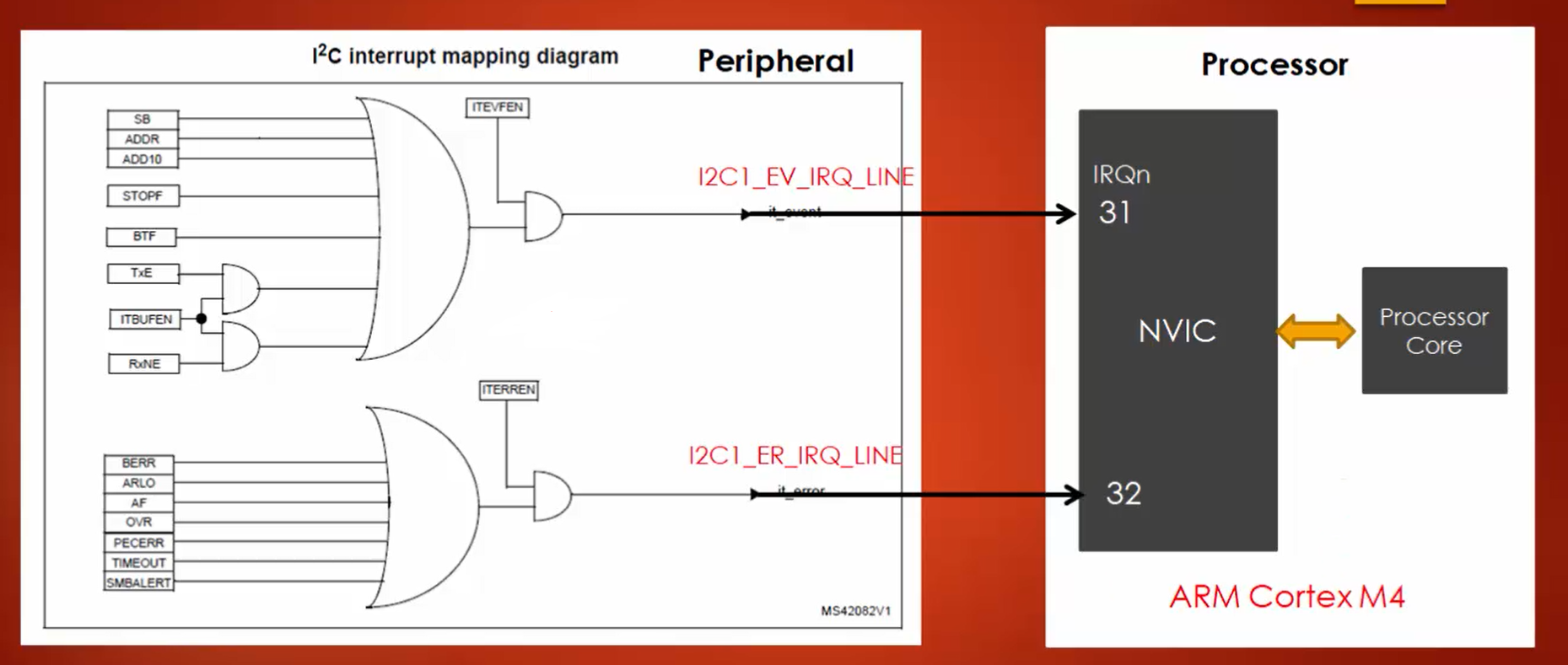
If you consider I2C1 peripheral, then the first line is called I2C1_EV_IRQ_LINE. Interrupts generated by all the events marked in Figure 4 are sent over I2C1_EV_IRQ_LINE connected to the IRQ number 31 in the NVIC. The remaining events in Figure 4 deliver the interrupt to the processor over the I2C1_ER_IRQ_LINE line, which is connected to IRQ number 32.
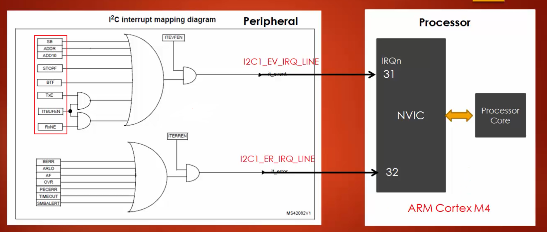
Since the logical gate in Figure 3 is an AND gate, the control bits connected to the gate must be enabled to deliver the interrupts to the processor.
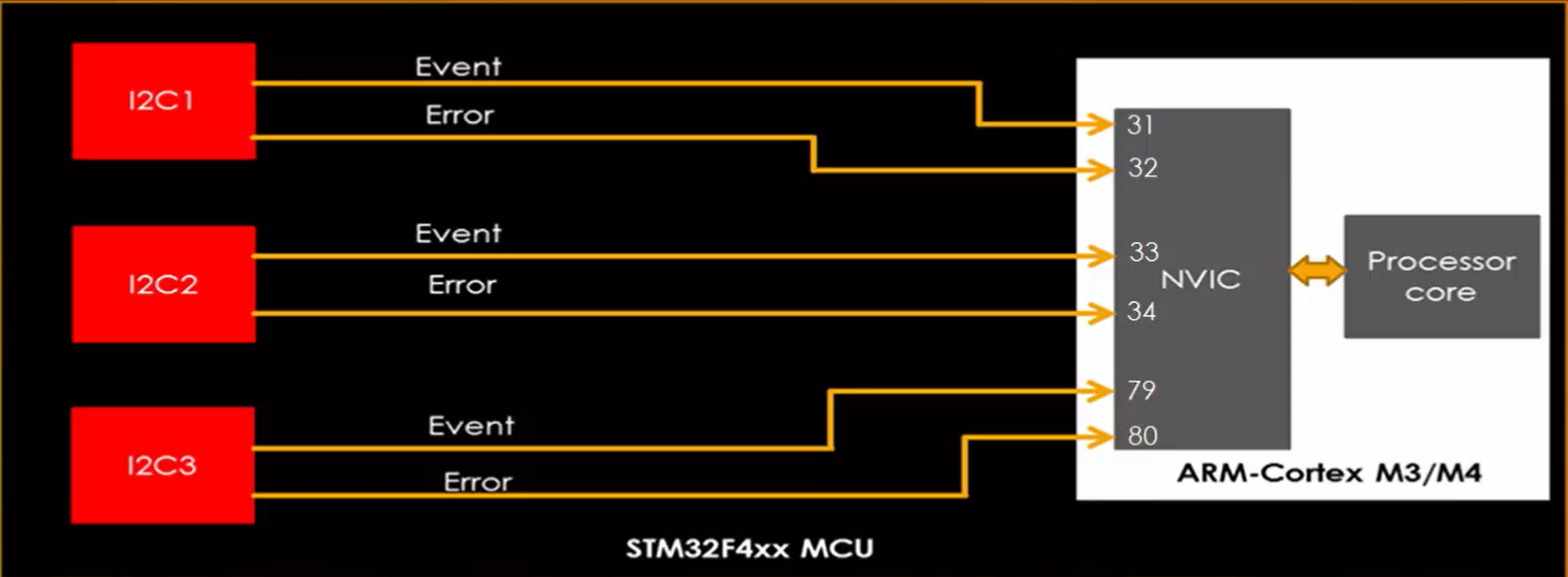
Figure 5 shows how different I2C peripherals deliver their interrupts to the processor.
- I2C1 delivers interrupt on 31 and 32 IRQ numbers.
- I2C2 delivers interrupt on 33 and 34 IRQ numbers.
- I2C3 delivers interrupt on IRQ numbers 79 and 80.
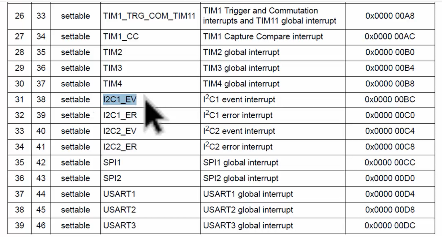
IRQ numbers are specific to MCUs, and you can get that details from the vector table of your RM (Figure 6).
In the following article, let’s see I2C errors and importance of BUSY flag.
FastBit Embedded Brain Academy Courses
Click here: https://fastbitlab.com/course1

