STM32 SPI Hardware and Software slave managements
In this article, let’s explore STM32 micro controller’s two types of slave management.
- Software slave management
- Hardware slave management
Software slave management
There is one bit called SSM bit in the SPI control one register (SPI_CR1). To use software slave management or software NSS management, make SSM bit as 1. So, software slave management or hardware slave management can be set using an SSM bit in the SPI control one register.
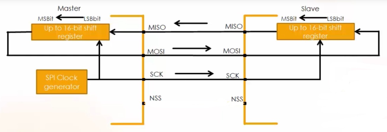
Let’s consider the scenario from Figure 1. There is one master device and one slave device.
Here, the slave select pin not used. But if you want to make this slave select to communicate with the master, then NSS has to be grounded. In this case, you can select software slave management for the slave device. Then what happens is, salve select information is driven internally by SSI bit value in the SPI control one register(SPIx_CR1). The external NSS pin is free for other applications. So, if SSM=1 and SSI=0 then the NSS pin will ground internally. That means the slave is selected, and then the salve can communicate with the master. So, here you need not use the NSS pin.
If SSI=1, then NSS pin will pull to high or VDD and if SSI=0, then NSS pin will pulled ground or 0.
Hardware slave management
In this case, if you want to use a slave select pin, then you are using hardware to control the slave select. Here SSM=0, then SSI has no meaning.
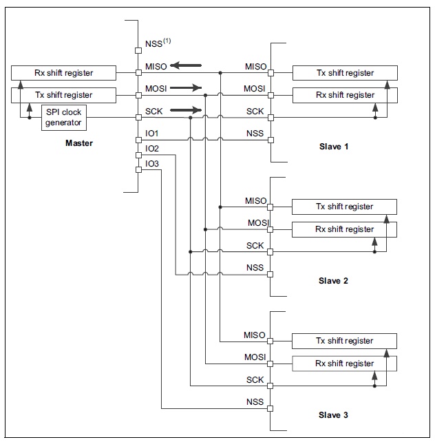
From Figure 2. There are one master and three slave devices. Here software slave management doesn’t work because the master has to select the slave first to which it wants to communicate then it has to do the data communication. By using different IOs of the master, one can drive the slave select pins of the slave device.
IO1 of the master connects to the slave1, IO2 of the master connects to the slave2, and IO3 of the master connects to the slave3.
Suppose, if the master wants to communicate with the slave2, then the master will make IO1 and IO3 line as high and IO2 line as low. When the IO2 line is as low, the NSS pin of slave2 will be grounded, and slave2 will activate. Slave1 and slave3 are in high impedance state so data will be received only by slave2.
When there are one master and multiple slaves, you cannot use software slave management. The NSS pin of the master is connected to +VDD to avoid some errors otherwise leave that pin as unconfigured. If the NSS pin, configured by using GPIO alternate functionality, then connect NSS pin to +VDD.
FastBit Embedded Brain Academy Courses
Click here: https://fastbitlab.com/course1