I2C IRQ handler implementation Part 6
In this article, let’s handle the interrupt generated by the setting of the RXNE flag.
Handling steps for the interrupt generated by the RXNE flag is similar to the handling of an interrupt generated by the TXE flag.
Steps to be followed when the RXNE flag is set:
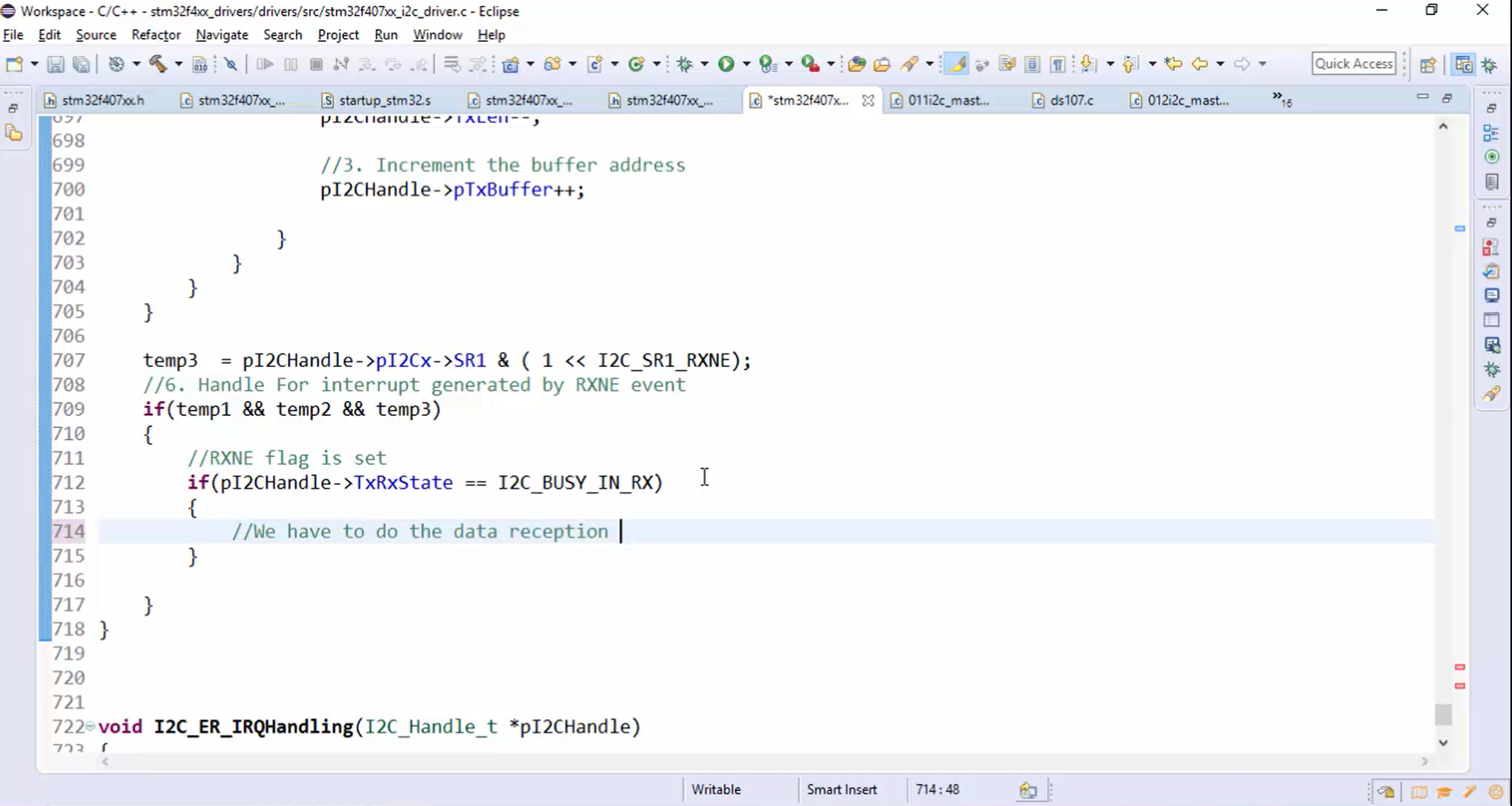
- When an RXNE flag is set, you have to do the data reception.
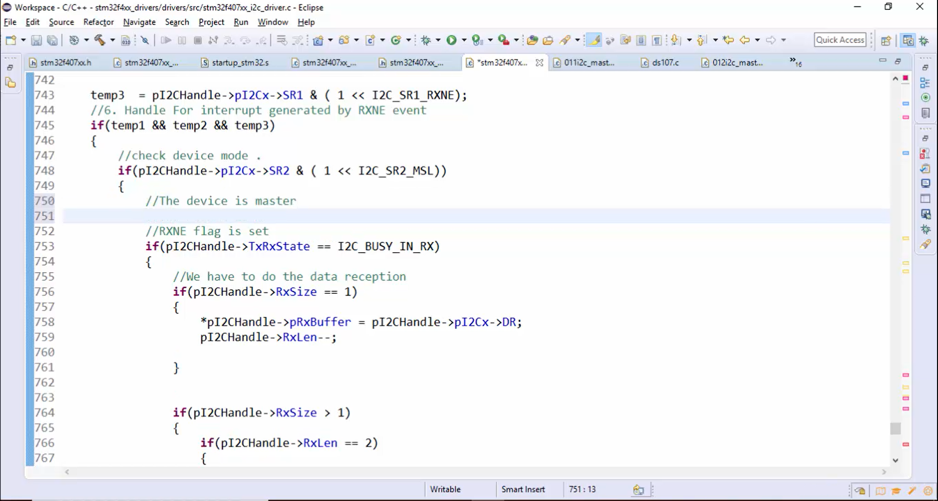
- Before starting the data reception, first, confirm the application’s state. The data reception must begin only if the application state is busy in RX. Let’s check the application’s state by using the if statement, as shown in Figure 1.
In the case of blocking API or receive data API, there are two separate cases for the data reception.
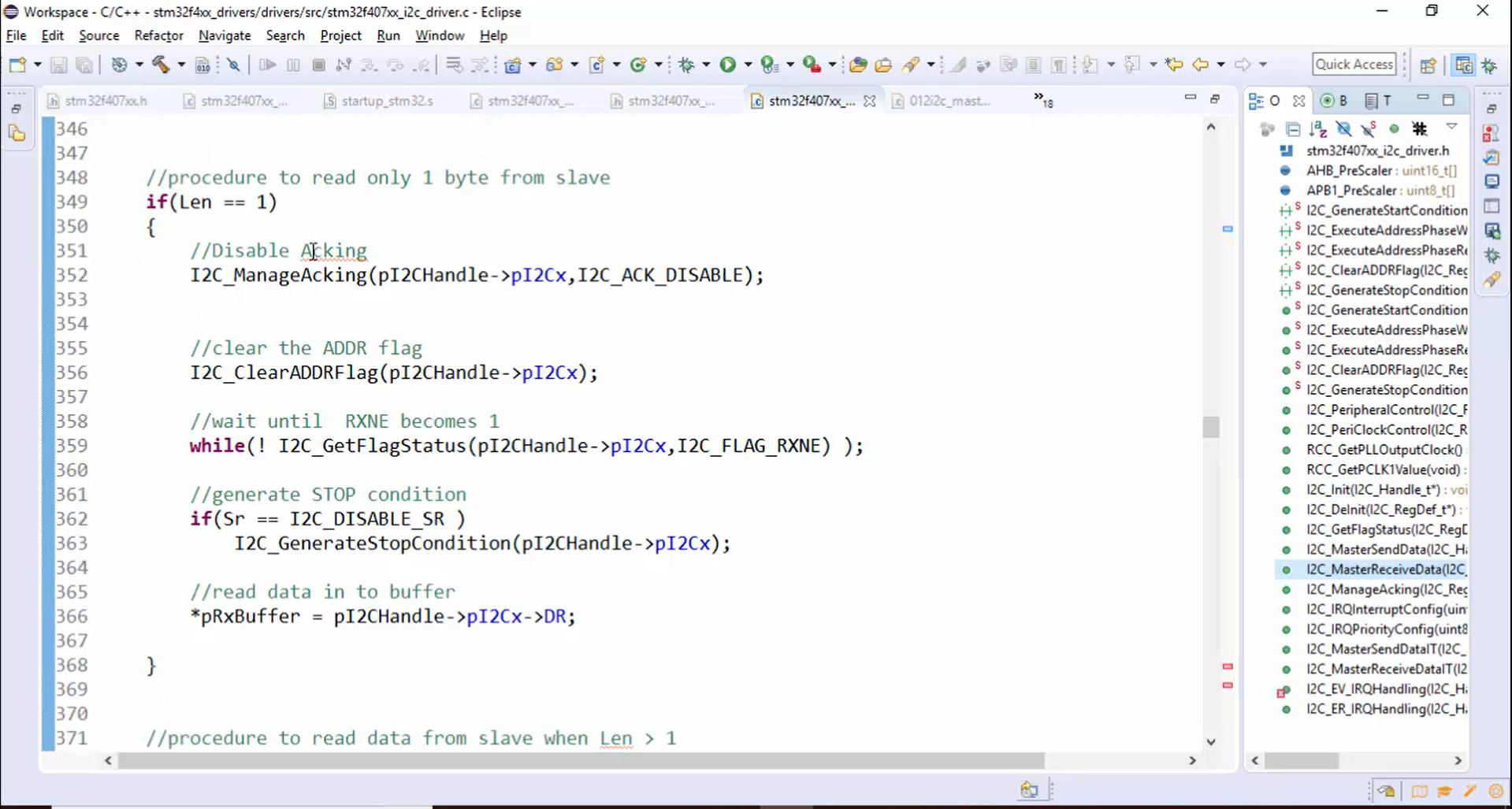
- Case 1: Length is equal to 1 (Figure 2).
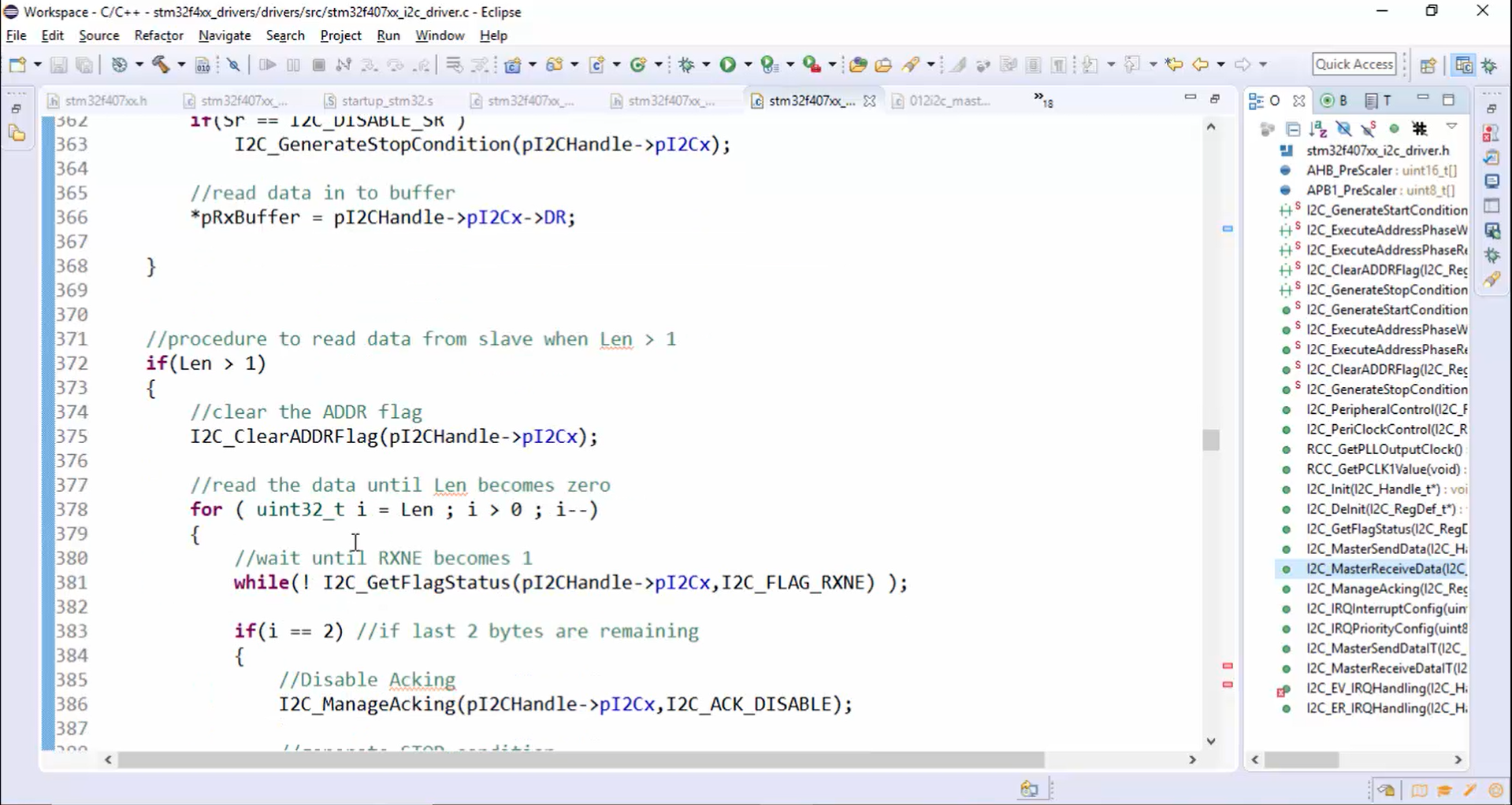
- Case 2: Length is greater than 1 (Figure 3).
Similarly, you have to perform the data reception when the RXNE flag is set.
- Steps for the data reception is as follows:
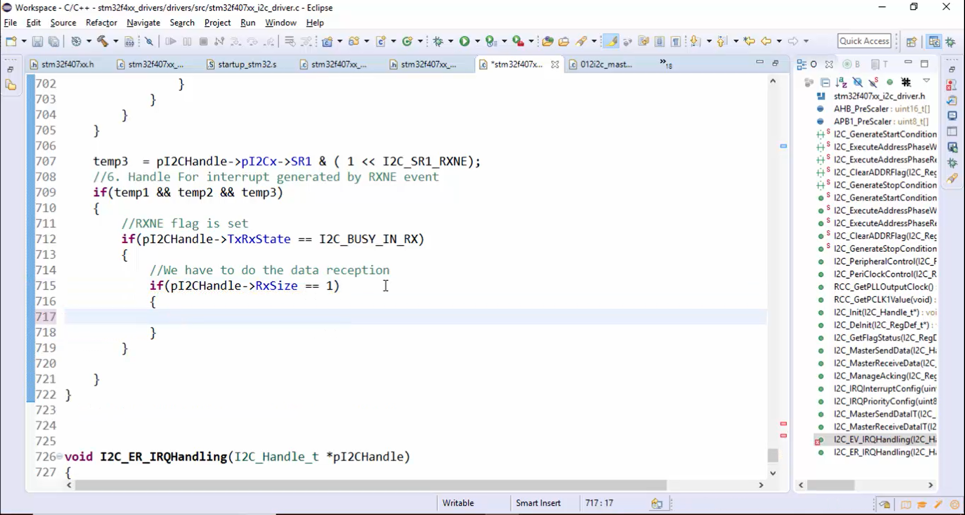
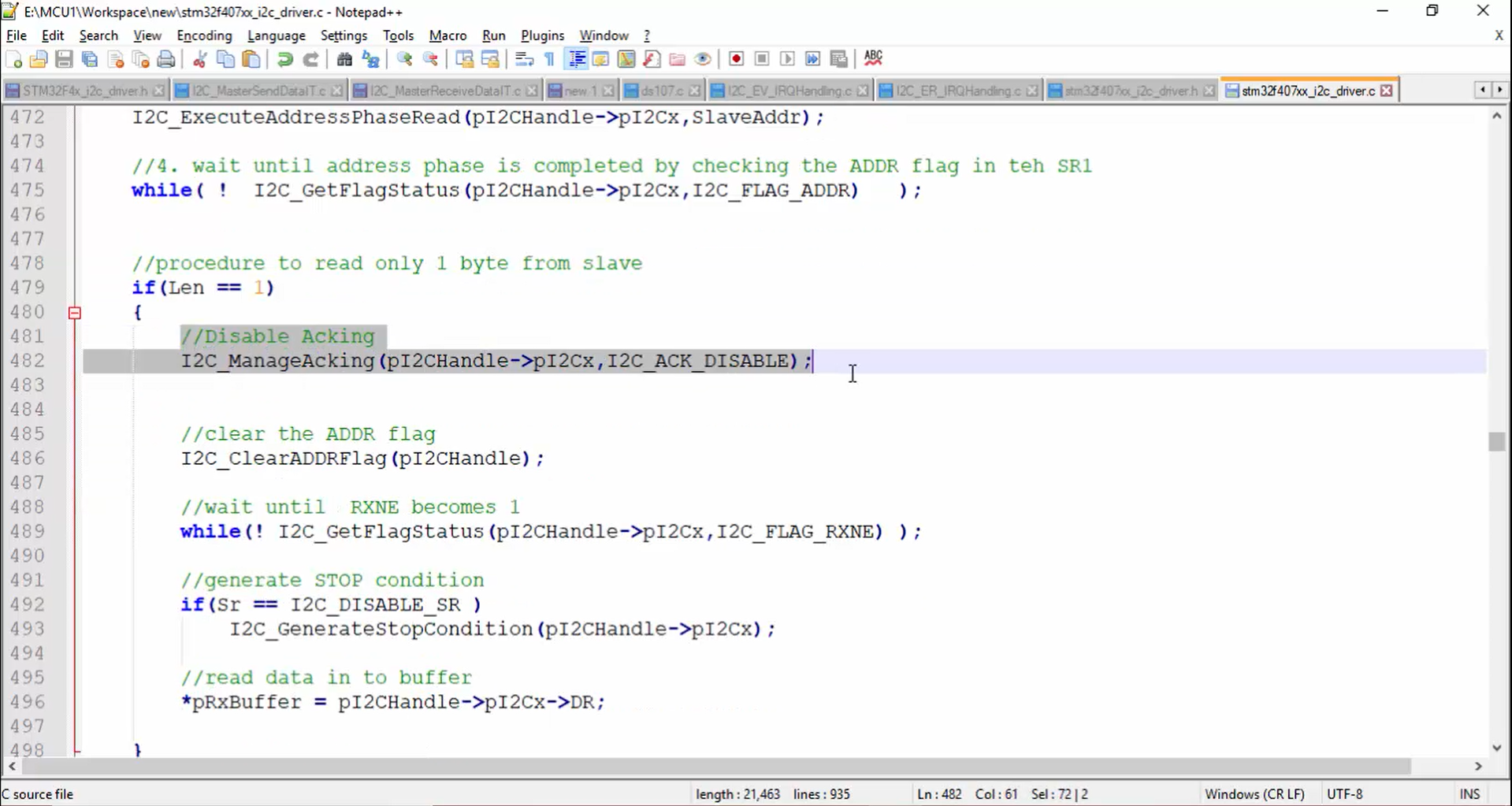
1. Check whether the length (RxSize) is equal to 1 (Figure 4).
2. Refer to the master receive data API in Figure 5. Before the data reception begins, you have disabled the Acking and then cleared the address flag.
In a similar way, you have to implement the non-blocking API.
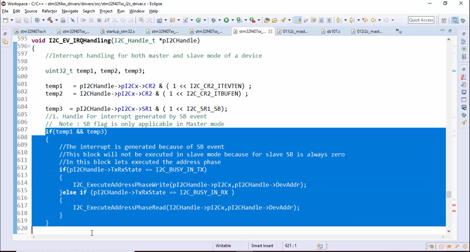
3. When the transmission begins, the first flag which is going to be set is SB (start bit), which means first, the control will execute the block shown in Figure 6. After that ADDR flag is set, and the block shown in Figure 7 will get executed.
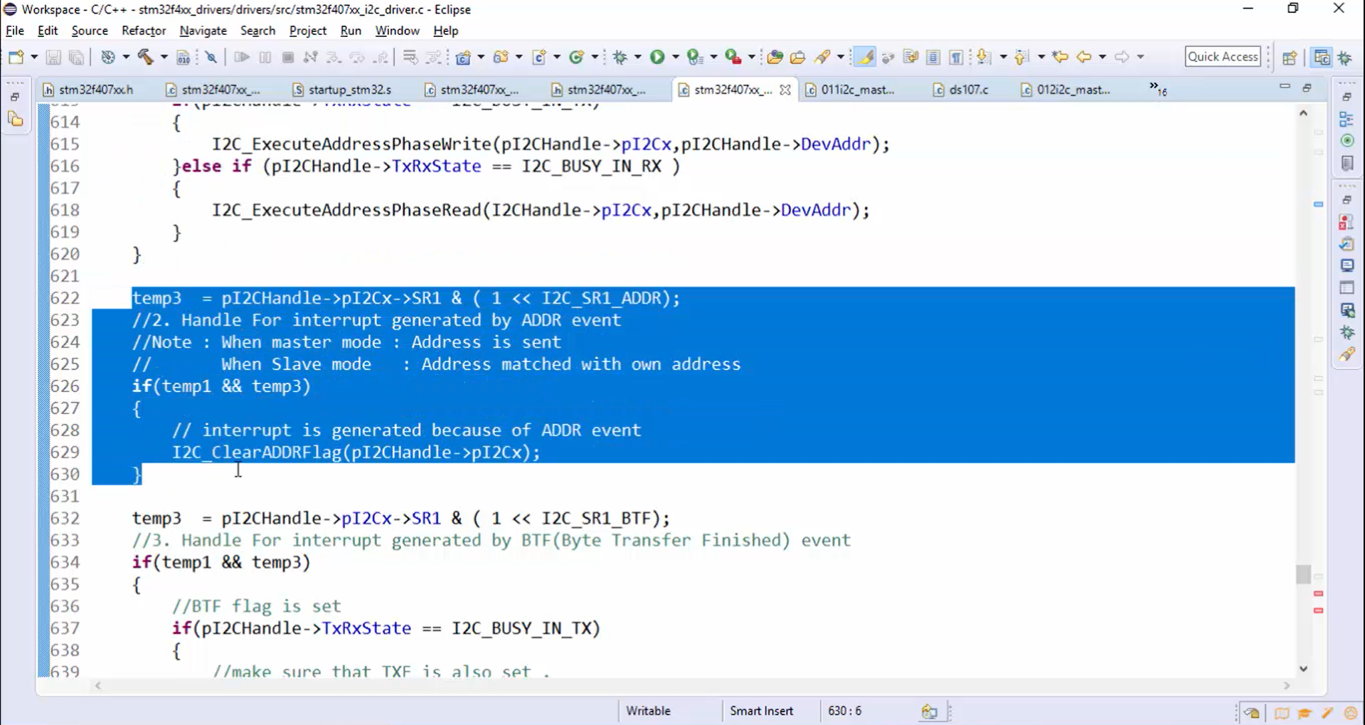
4. Observe Figure 7. The ADDR flag is cleared while handling the interrupt generated by the ADDR flag, which is actually wrong because before clearing the ADDR flag, you need to disable the Acking. To overcome this problem, you need to change the I2C_ClearADDRFlag() function as follows:
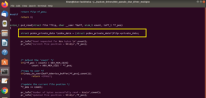
- Change the parameters of I2C_ClearADDRFlag() to a pointer to the handle instead of a pointer to the base address of the peripheral (Figure 8) because we have to access the member elements of the handle structure.
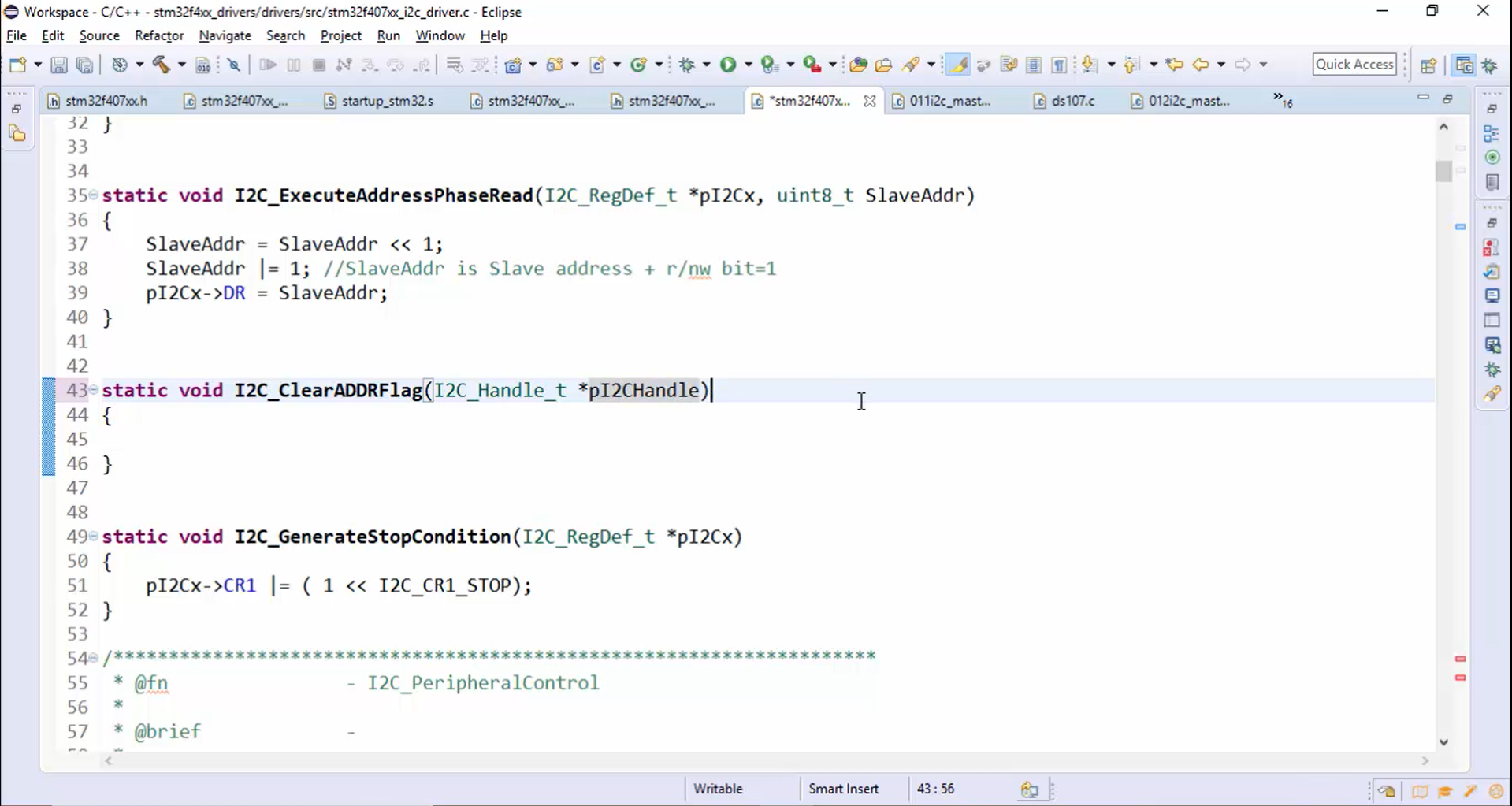
- Change the parameters of the I2C_ClearADDRFlag() prototype, as shown in Figure 9.
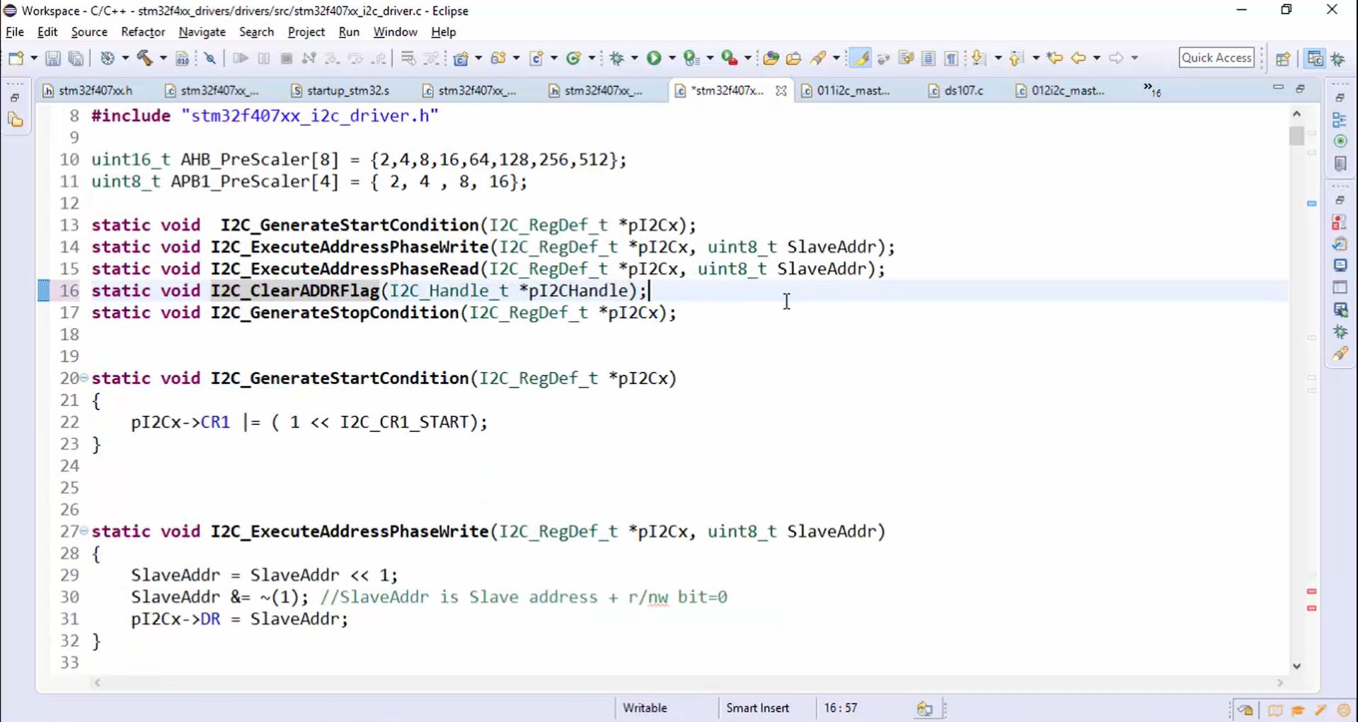
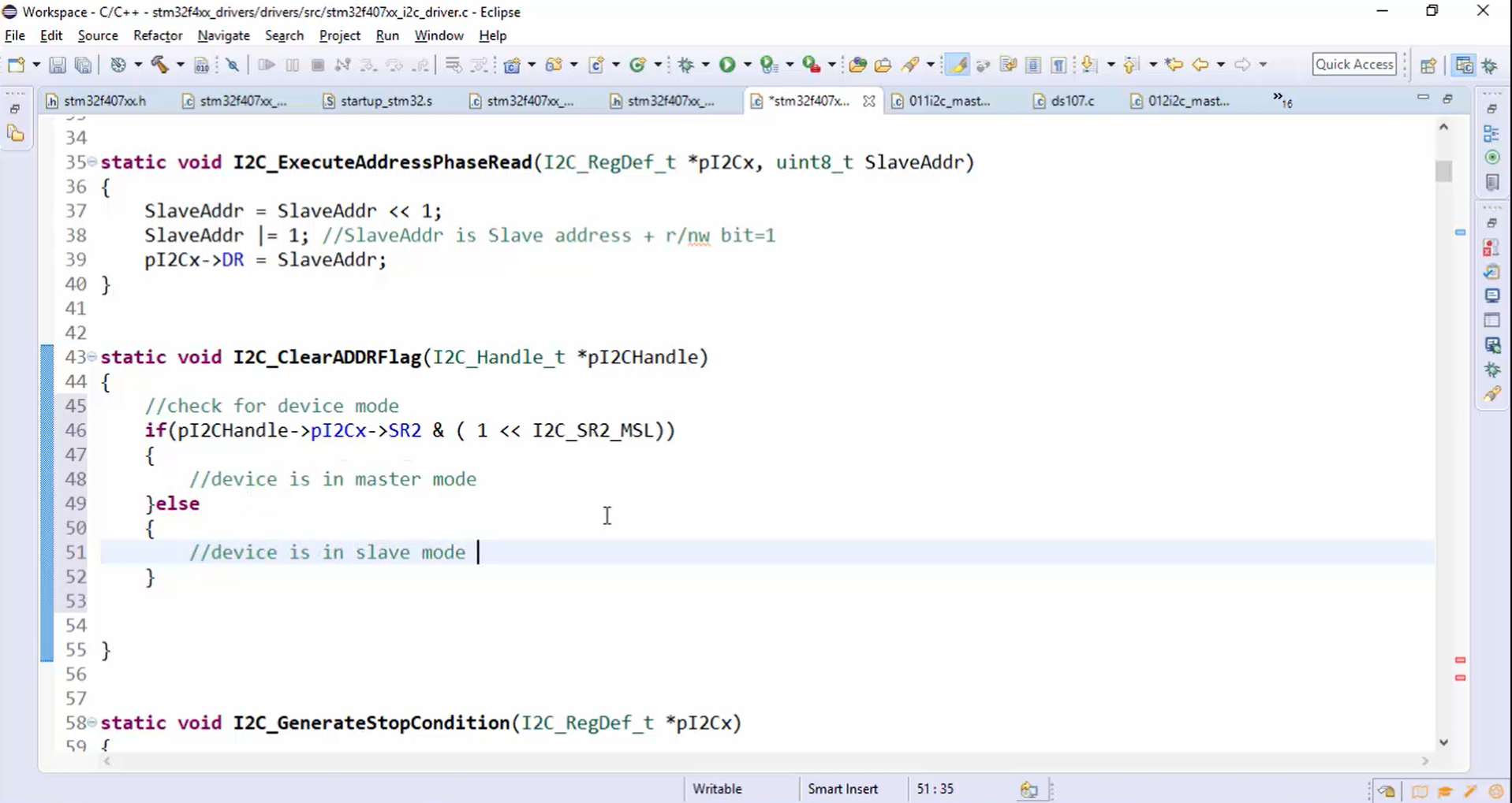
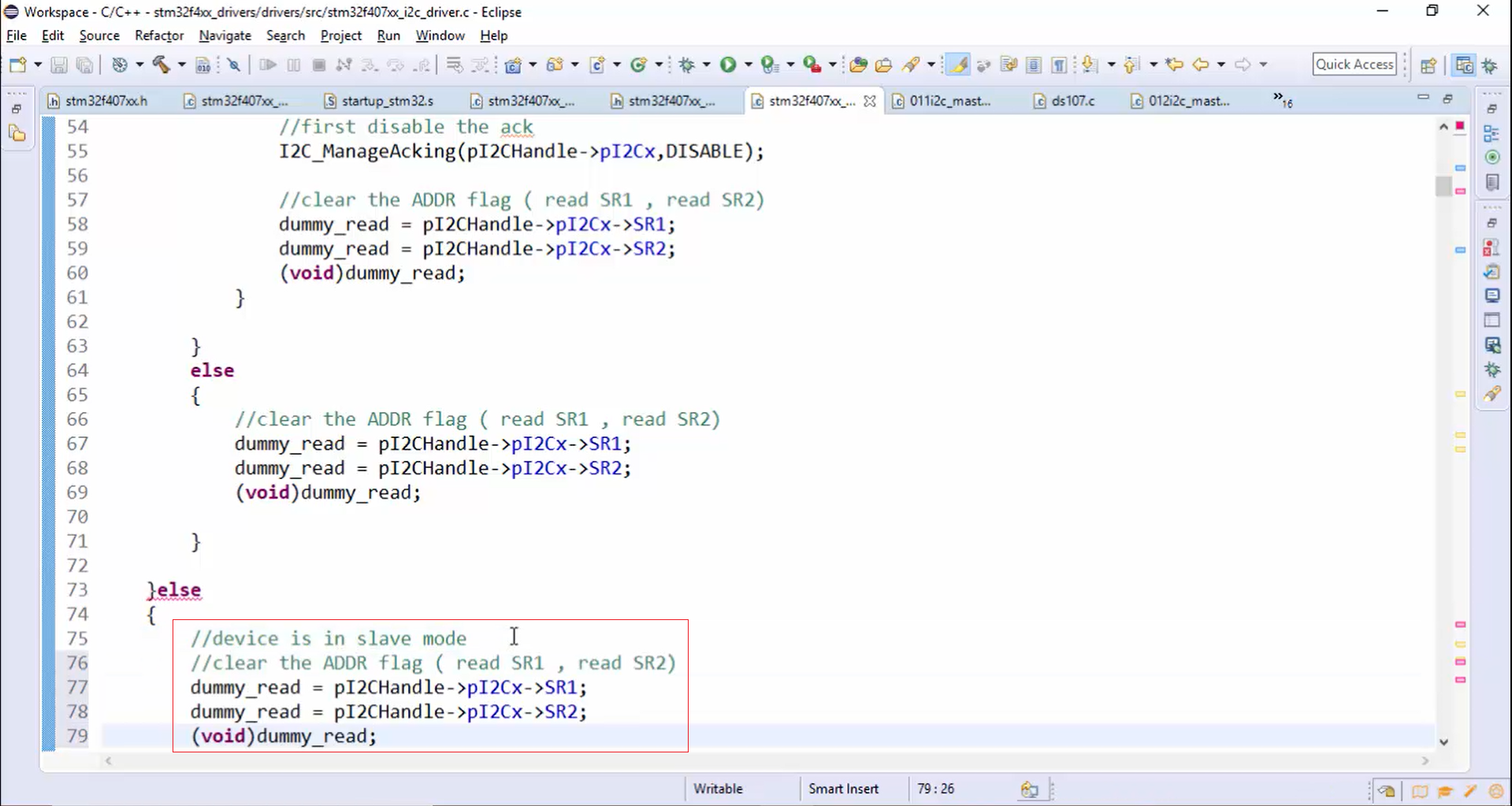
- Check for the device mode: Since we are going to code according to the mode of the device, first check whether the device is in master mode or slave mode. For that, you have to check the 0th bit of the SR2 register, as shown in Figure 10.
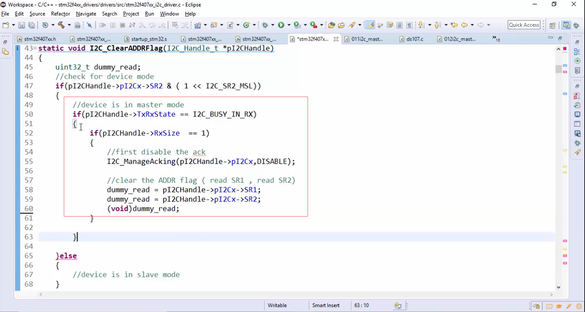
- If the device is in master mode (Figure 11), then check for the application’s state. If the application’s state is busy in RX and the RxSize = 1, then disable the ack. Once you disable the ack, the next step is to clear the ADDR flag. Look at Figure 11. The unused variable dummy_read is typecast to void. Otherwise, the compiler will issue warnings saying that the variable dummy_read is unused.
- If the device is in master mode and the application’s state is not busy in RX, then you can straight away clear the ADDR flag, as shown in Figure 12.
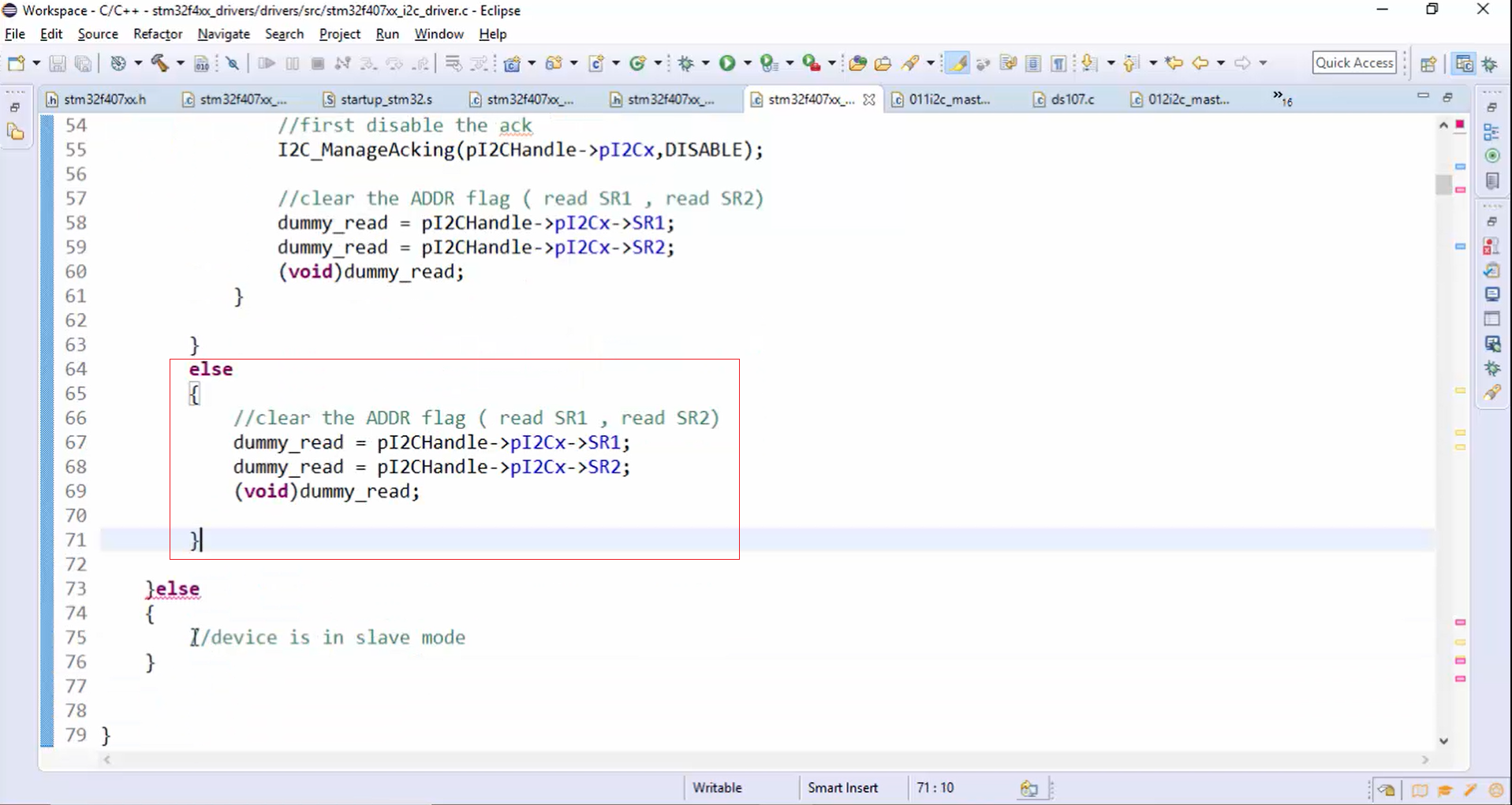
- If the device is in slave mode, then straight away clear the ADDR flag, as shown in Figure 13.
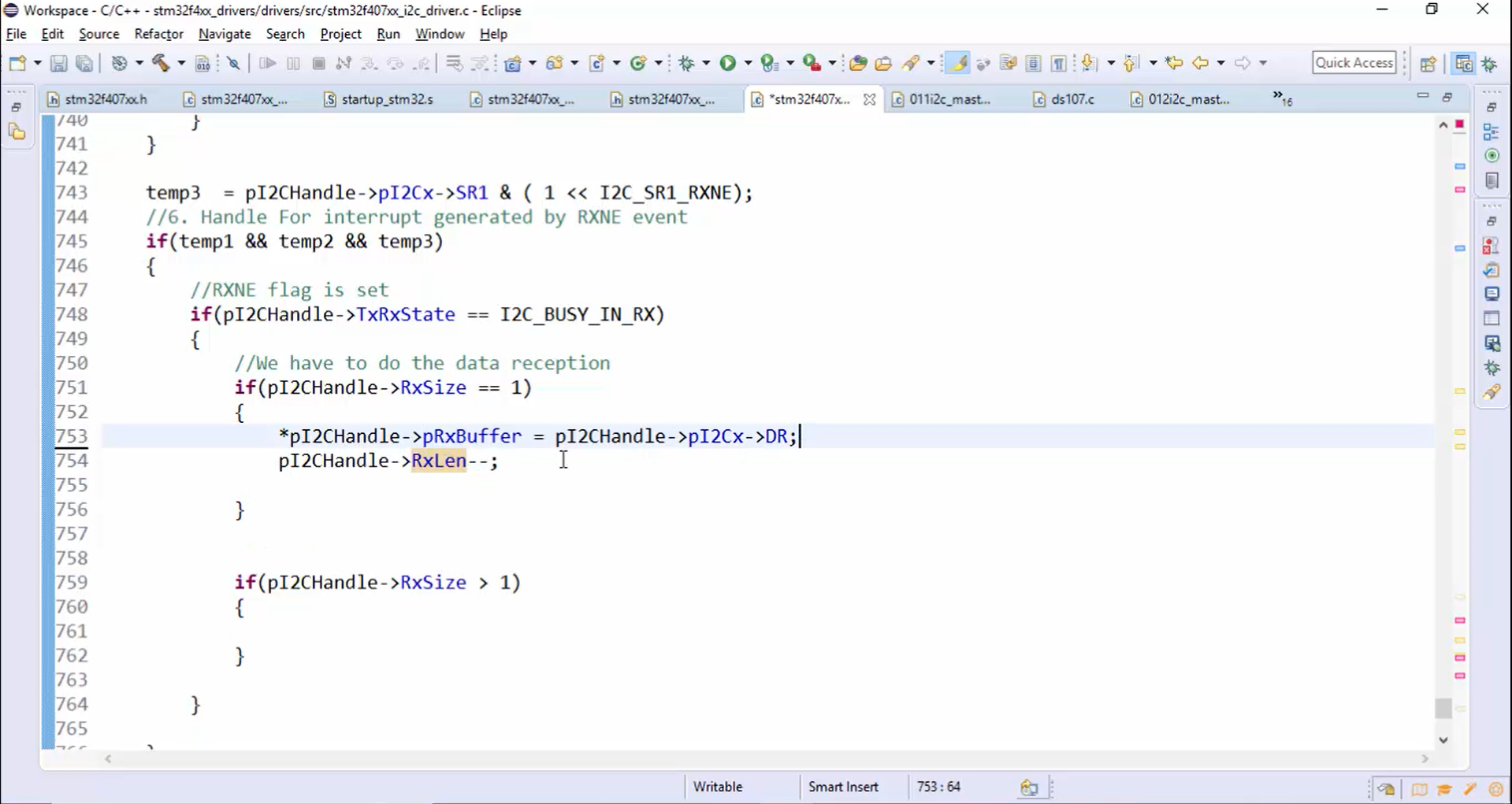
5. Go back to the ISR handling of the RXNE. When RxSize=1, read one byte into the RxBuffer from the DR and then reduce the length, as shown in Figure 14.
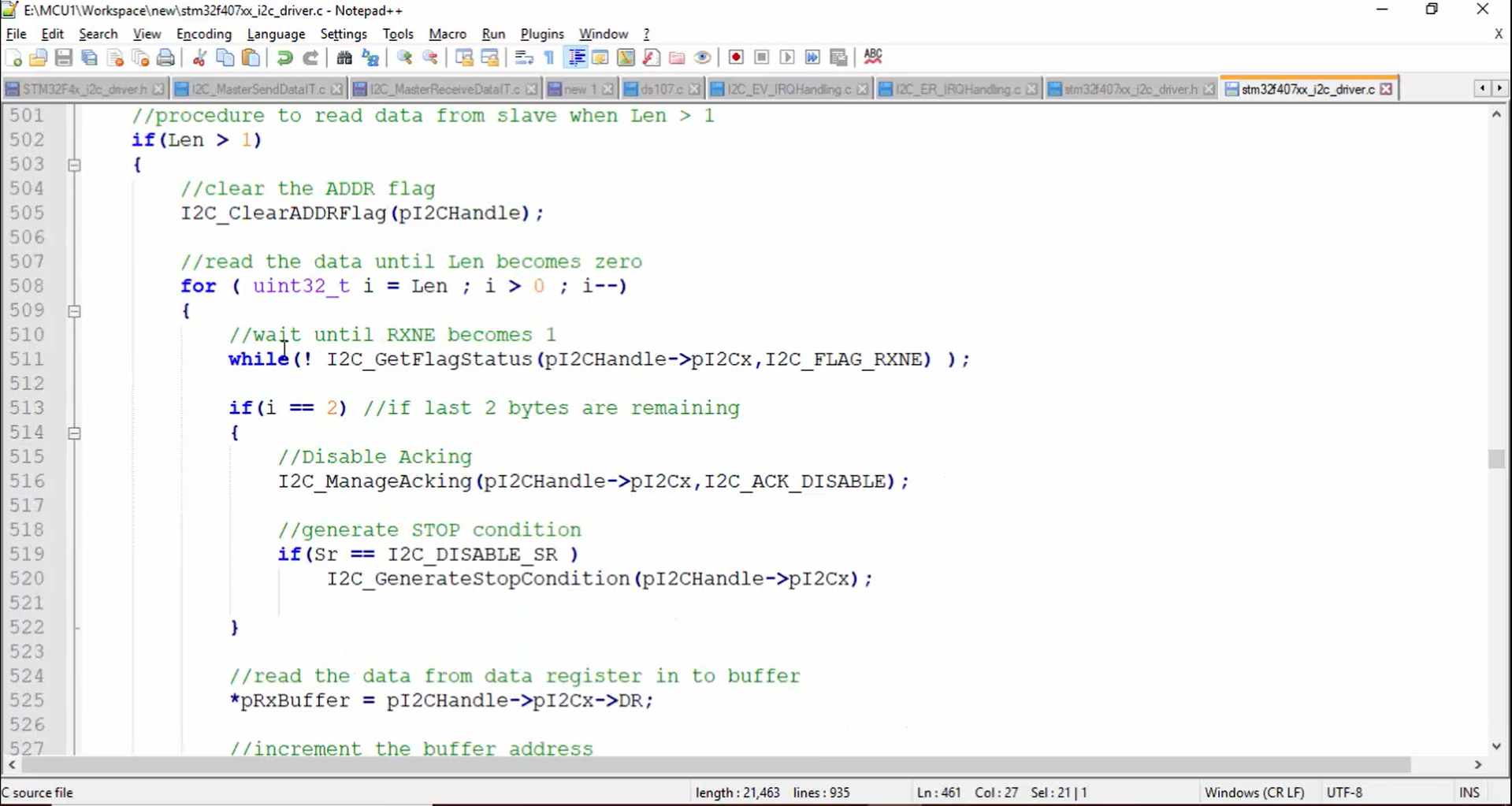
6. Refer to the master receive data API in Figure 15. When the length is greater than 1, we have done the following things:
- Clear the ADDR flag.
- Read the data into the buffer.
- When length reaches 2, disable the Acking.
- Generate the stop condition.
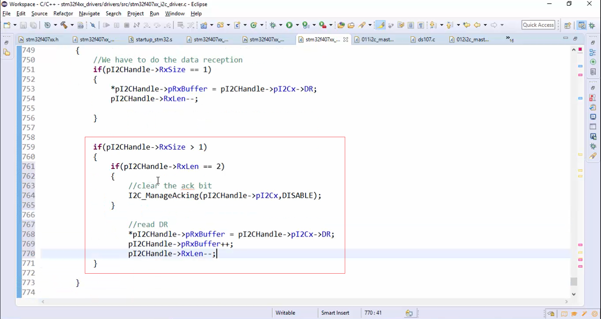
Now, you have to do the same things in the case of interrupt mode, as shown in Figure 16. When the length reaches 2, you can turn off the Acking. Otherwise, keep on reading the data into the data buffer and decrementing the RX length.
7. When the RX length is equal to zero, then that is the indication for us to close the I2C data reception.
Steps to close the I2C data reception:
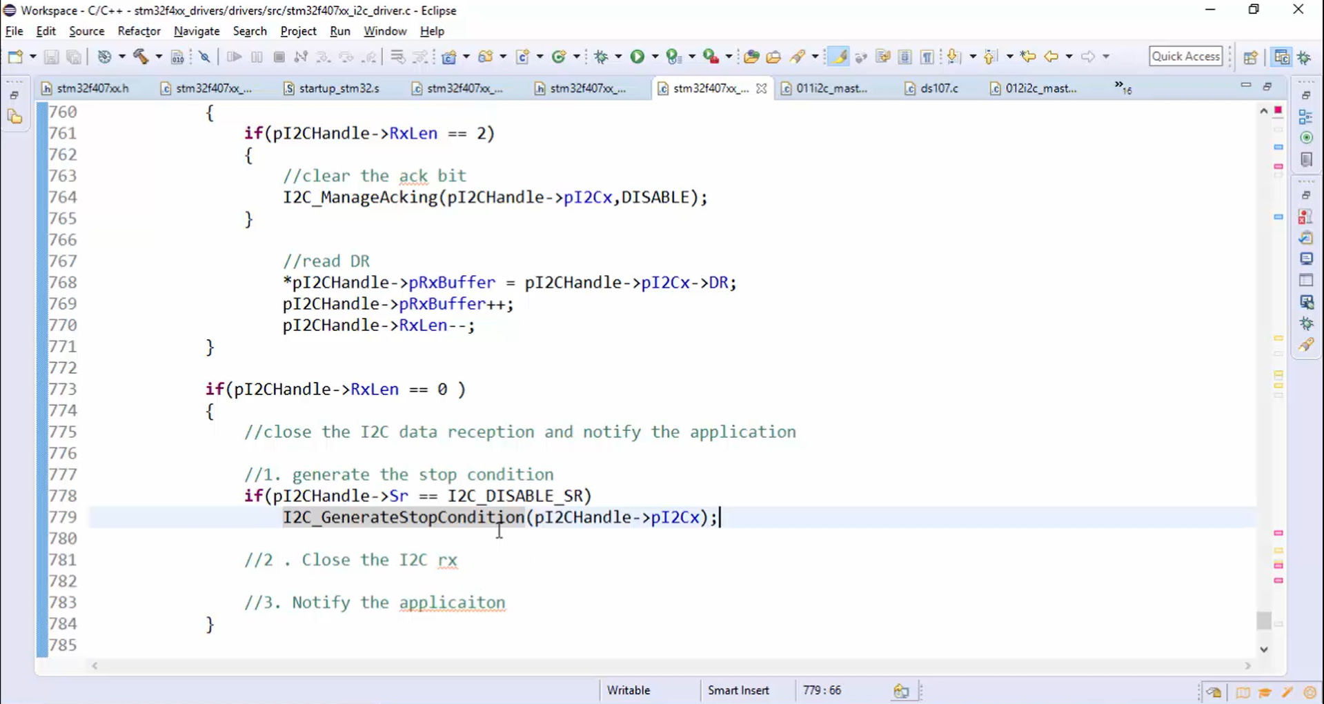
- Generate the stop condition (Figure 17).
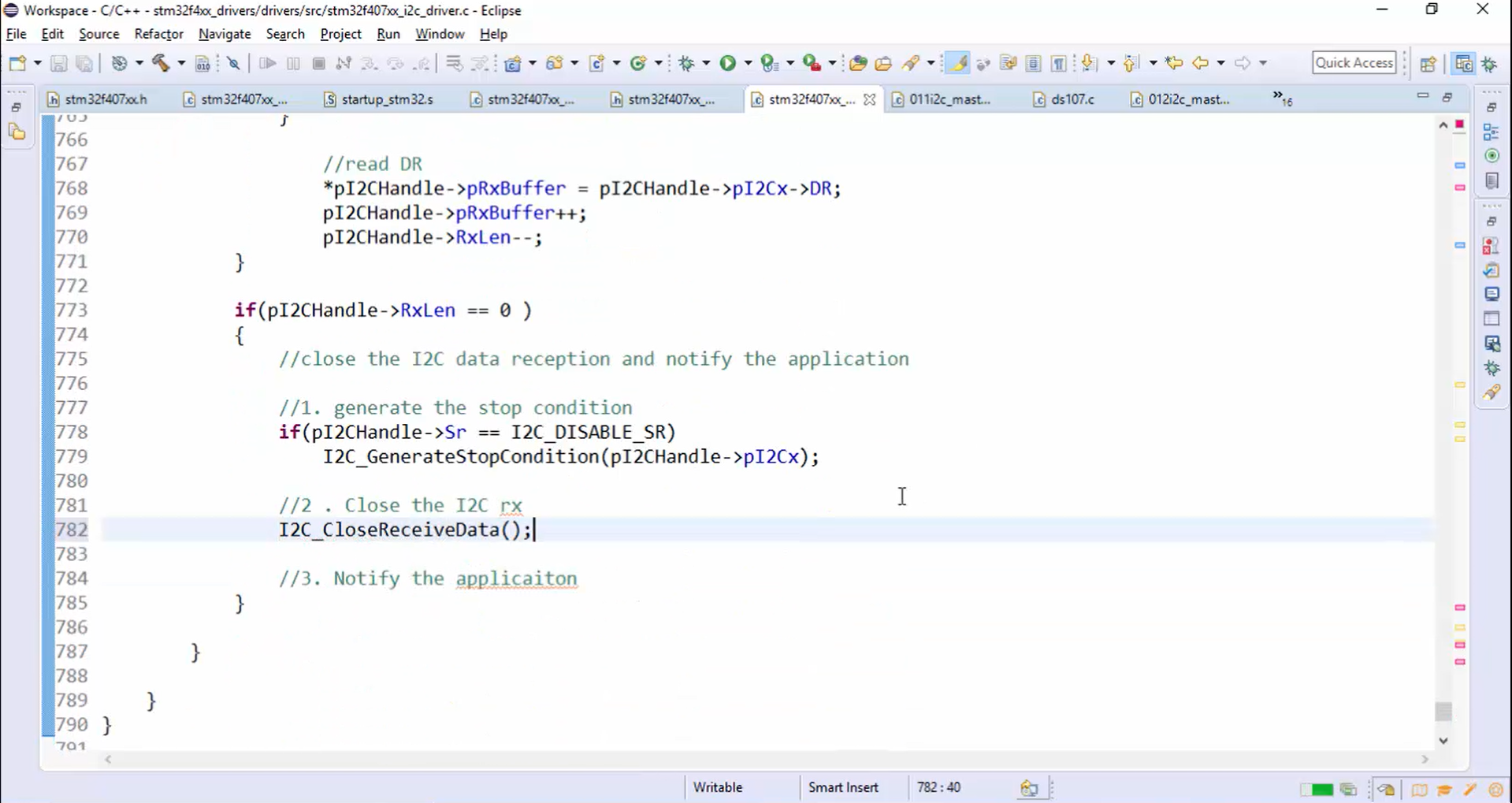
- Close the I2C RX: To close the I2C RX, implement an API called I2C_CloseReceiveData(), as shown in Figure 18.
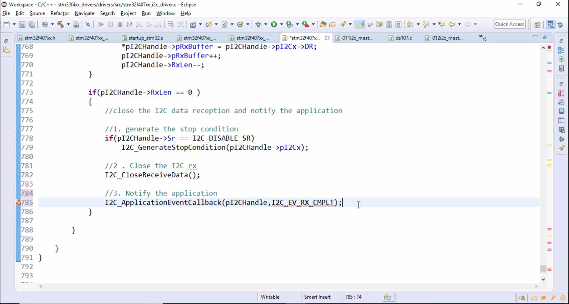
- Notify the application (Figure 19).
8. All the tasks in Figure 14, Figure 16, Figure 17, Figure 18, and Figure 19 must be performed only when the device is master because we are creating the API for I2C master receive data. Therefore, before performing these tasks, you should confirm whether the device is master or not. You can ensure the device mode by checking the MSL bit of the status register at any point in time. If the MSL bit is set, you can say that the device is behaving as a master. Otherwise, the device will be in slave mode. This bit is set by the hardware as soon as the interface is in Master mode (SB=1) and cleared by the hardware after detecting the stop condition on the bus or loss of arbitration or when PE=0.
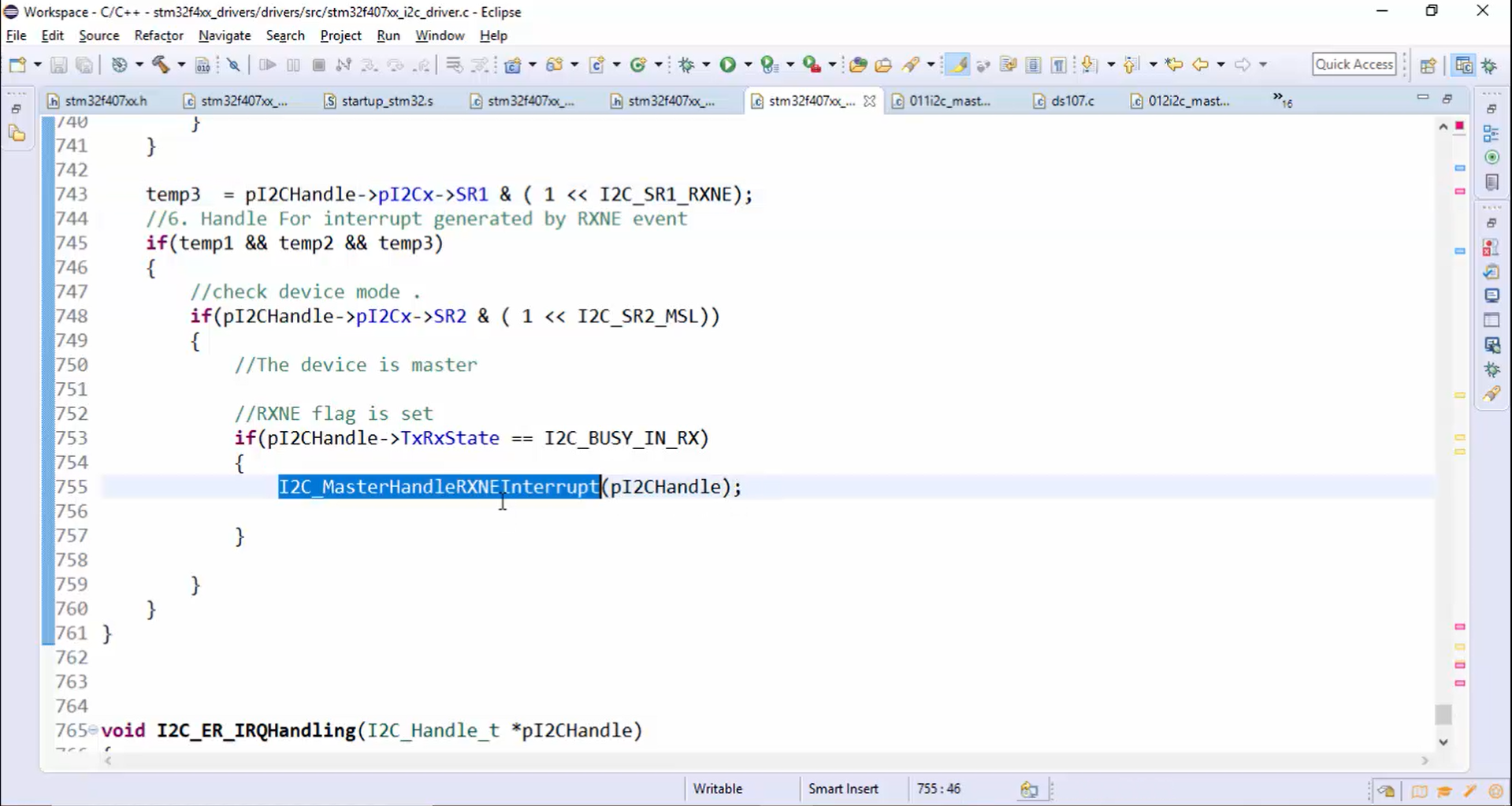
Now let’s check the device mode, as shown in Figure 20.
9. The code in Figure 20 is quite long. In order to understand properly, you can create a new helper function (I2C_MasterHandleRXNEInterrupt()) by removing all the codes written for data reception, as shown in Figure 21, and the function argument will be a handle variable.
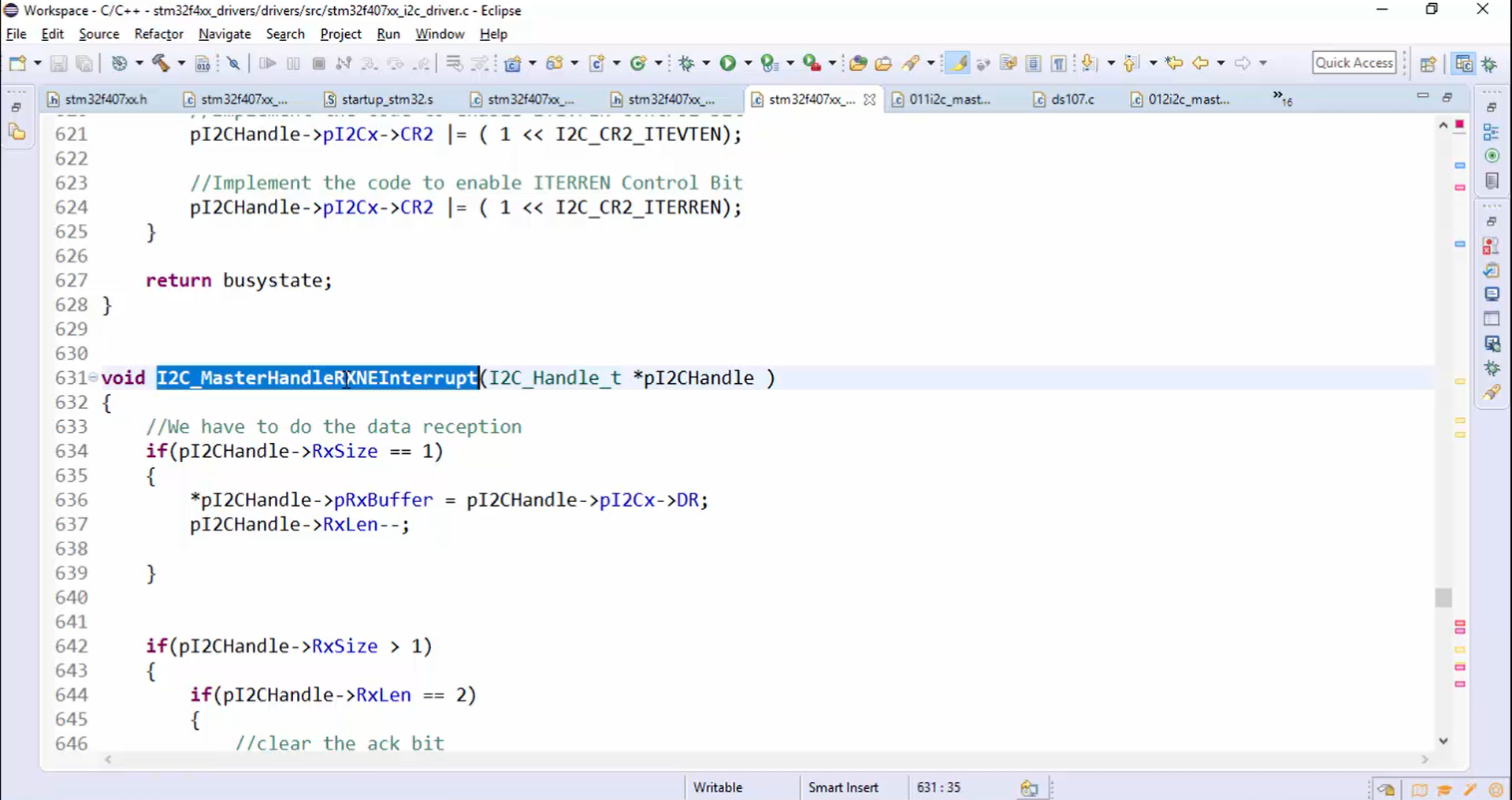
10. All the code required for the data reception is pasted inside the definition part of the helper function, as shown in Figure 22.
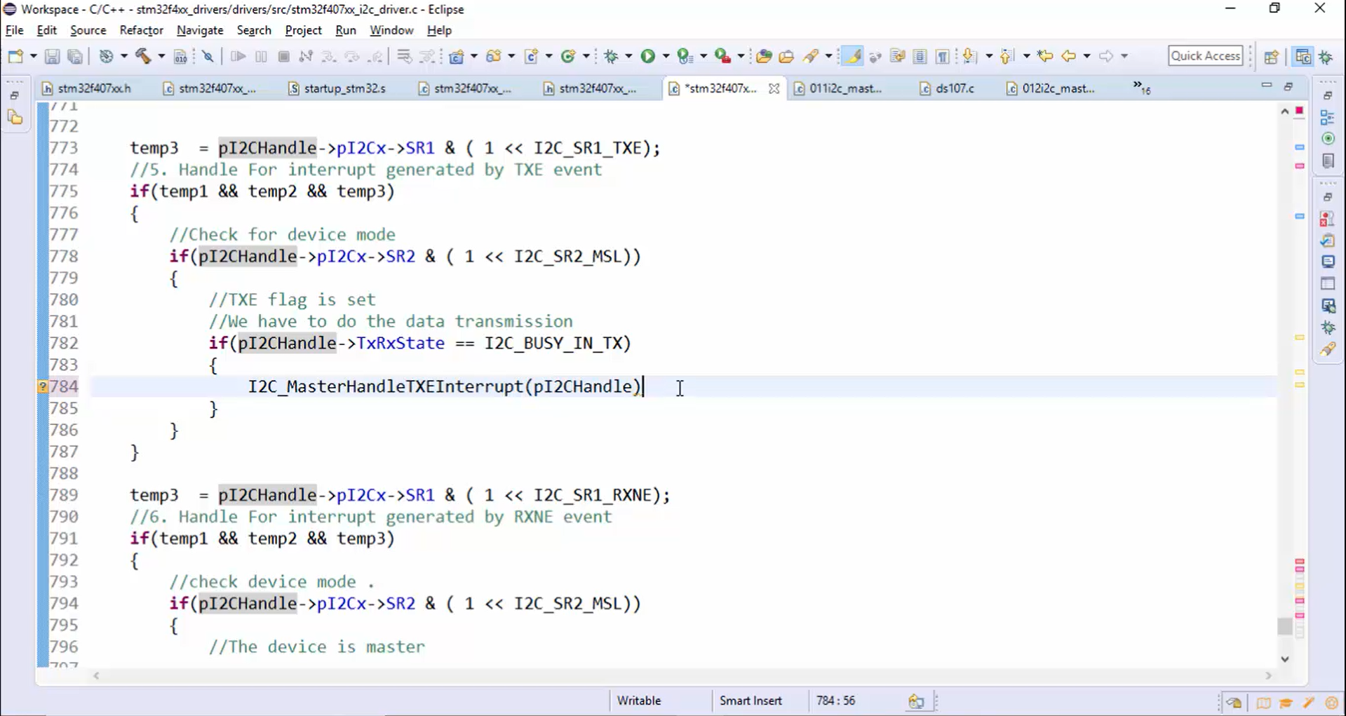
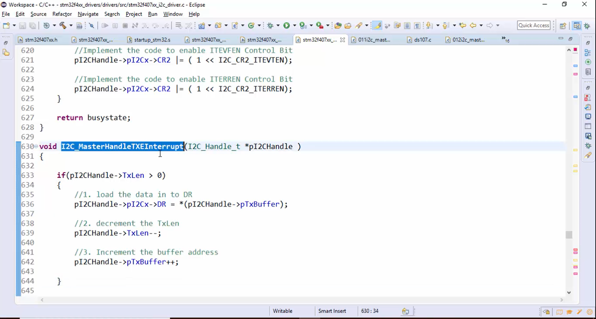
11. Similarly, create one more helper function in order to handle the TXE interrupt (Figure 23).
12. Call the helper function (I2C_MasterHandleTXEInterrupt()) from the IRQ handling, as shown in Figure 24.