About LTDC peripheral of STM32 MCU
In the previous article, we understood how to convert an image into C-Array, and how to adjust the pixel format in our application.
But, how that C-Array is getting transferred to the display module?
For that, the application uses the LTDC peripheral of the ST microcontroller.
LTDC stands for LCD-TFT Display Controller. This is one of the on-chip peripherals of the microcontroller.
Remember that, none of the microcontrollers used on NUCLEO boards have this LTDC support. So, before using this LTDC controller, you have to first configure it.
LTDC of the ST Microelectronics
Configure and enable the LTDC peripheral(LCD-TFT Display Controller) of the microcontroller
- LTDC of the MCU generates all synchronization and timing signals and transfers RGB components to the display.
- Display which has a display driver chip that interprets those signals and drivers the display panel to light the desired pixels.
Block diagram of LTDC
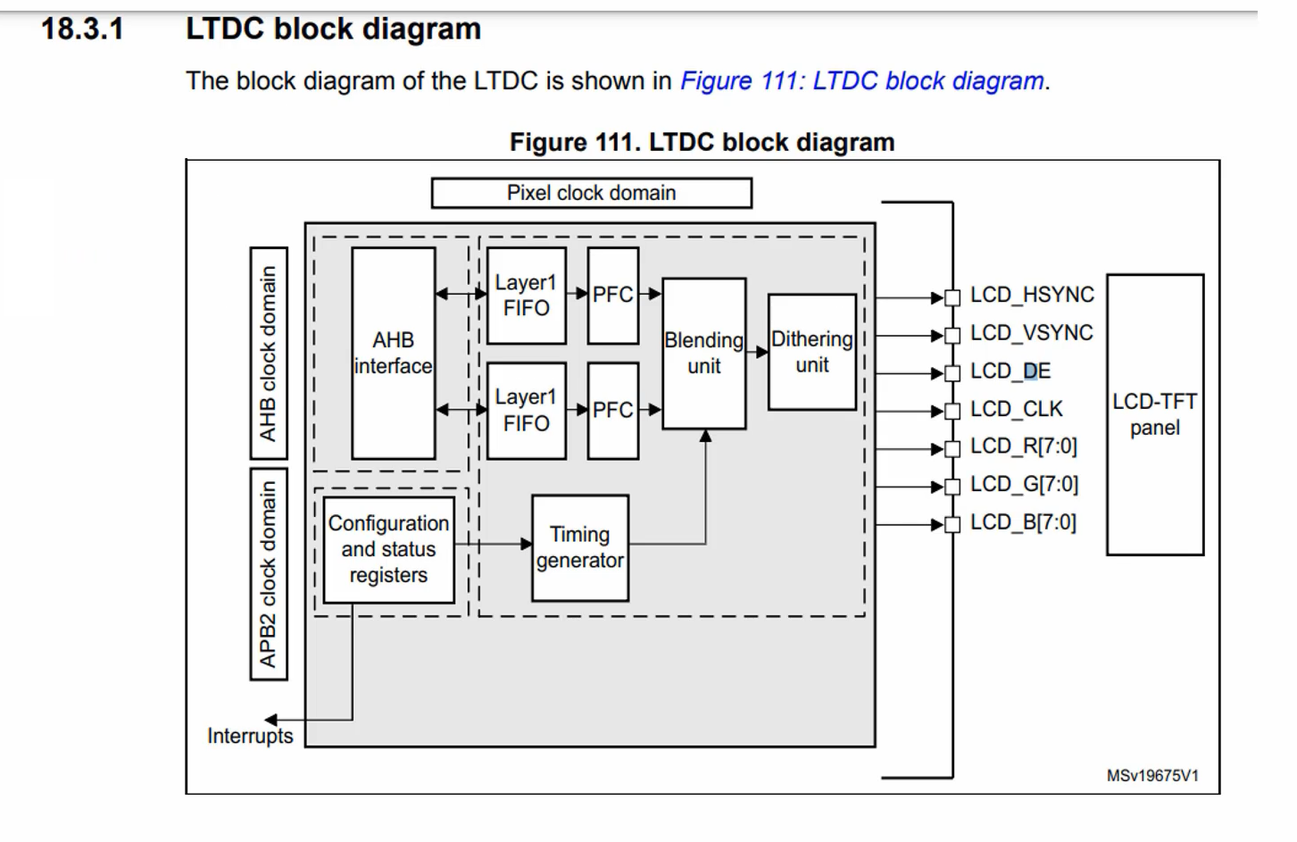
The block diagram of the LTDC peripheral is shown in Figure 1. It has some configuration register. In that configuration register, you have to configure the frame buffer address or your C-Array address. The frame buffer is a static one, the contents will not change, these are read-only data.
Once you configure the address, then you just have to enable this peripheral. There is no read function, and there is no send function, so you just have to enable the peripheral.
To get the LTDC section in the reference manual to explore more about this peripheral (page number 480 onwards).
So, it reads that memory location and gets the data as per the pixel format and it sends that data over the RGB interface to the display module(Figure 2).
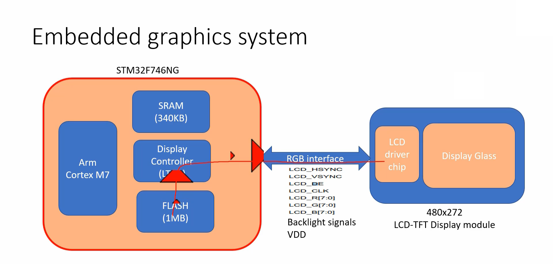
Here, the processor is actually not involved. LTDC takes care of that. So, LTDC sends the RGB values on its data interface.
You can see that(Figure 1), LCD_R, LCD_G, and LCD_B give 24 lines, 8 for each color component.
And LCD_HSYNC, LCD_VSYNC is synchronization, and LCD_CLK, and LCD_DE are clock signals. These signals are required by the display module. LCD_HSYNC signal tells where exactly the line starts, and LCD_VSYNC signal tells where exactly the frame starts, and LCD_DE signal tells when the data is valid and when the data is invalid, and LCD_CLK is a clock signal to the display module.
The goal of this article is, just to understand how that C-Array is getting transferred to the display module, and that is because of the LTDC peripheral which does the direct memory access.
Please note that, in this project, the project which is running on the STM32F429IDISCOVERY board uses LTDC. The project which runs on the STM32F746GDISCOVERY board also uses LTDC.
STM32F407DISCOVERY + SPI-based LCD module in this hardware combination, we are not using LTDC. Now, let’s see how things are working in this setup.
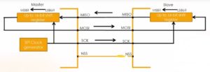
As you know, we are using SPI communication to send the pixel values or also called RGB data to the display.
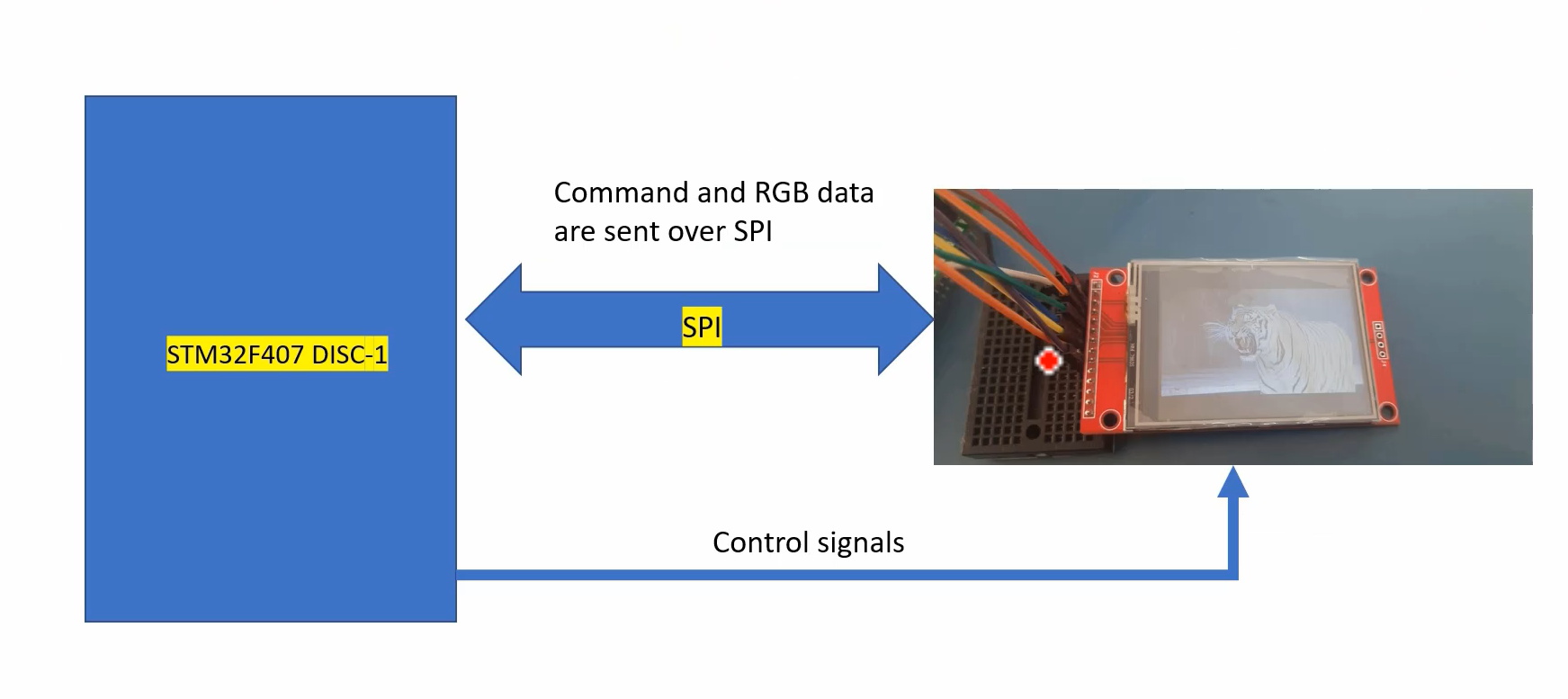
Look at Figure 4, this is how the frame buffer contents, which are there in the flash are sent to the display module over the SPI communication.
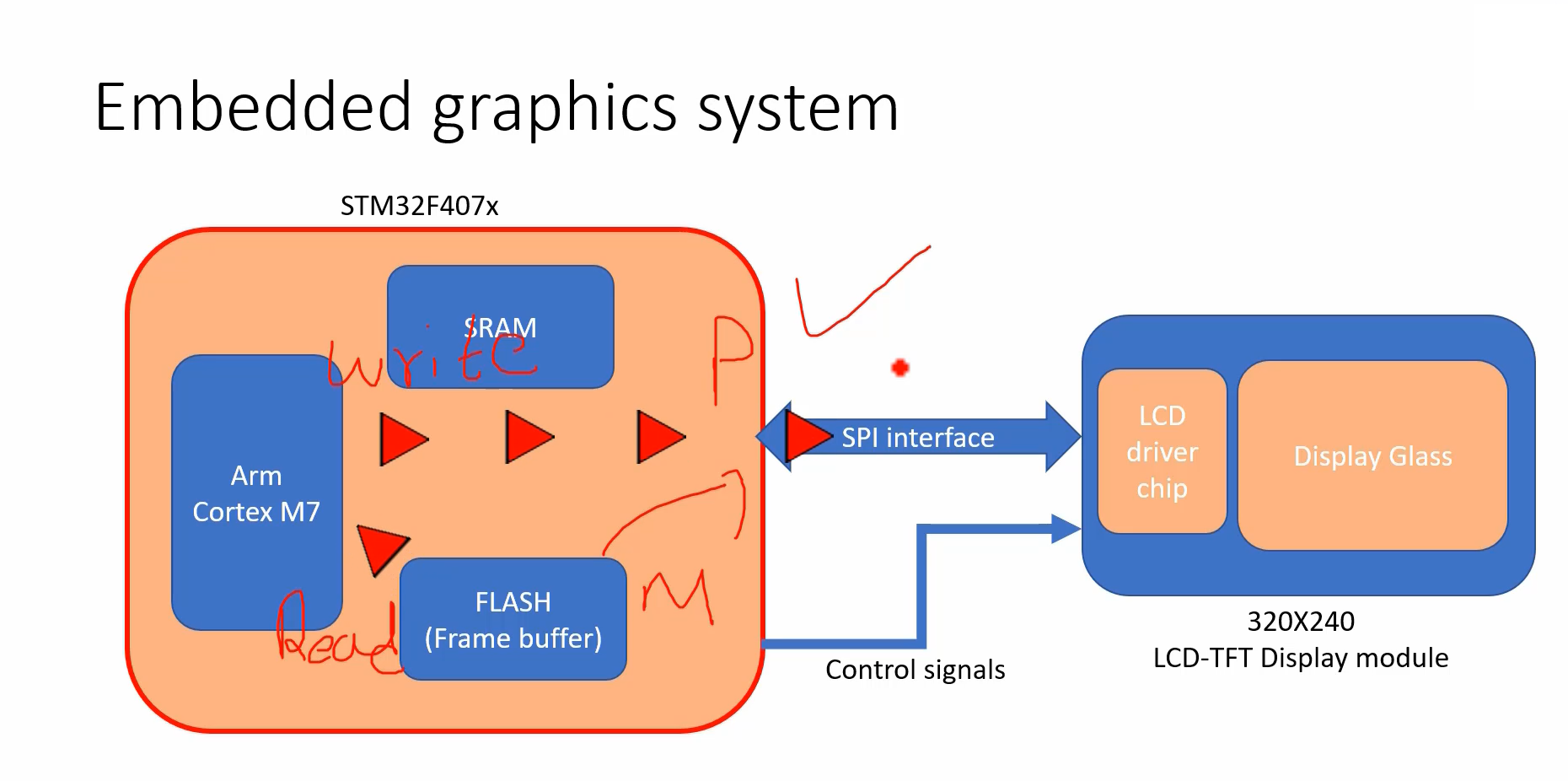
First, you must observe that there is no LTDC.
Here, we are reading the data from the Flash and we are writing to the SPI peripheral. So, you have to call a function SPI write or SPI transmit. Actually, the processor is involved here, because you are doing read and write operations.
But you can even use direct memory access here. You can do the memory-to-peripheral transfer using the DMA peripheral of the microcontroller. But, currently, in this project, DMA is not used.
In the following article, let’s understand various Display Interfaces.
Get the Full Course on STM32-LTDC, LCD-TFT, LVGL (MCU3) Here.
FastBit Embedded Brain Academy Courses
Click here: https://fastbitlab.com/course1

