Roaring tiger demo on STM32F407-DISC board with external LCD
In this article, let’s see the Roaring tiger demo on the STM32F407-DISC board with an external LCD.

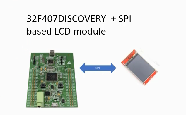
Here we are using an external LCD. That’s why you need to establish the connections first. So, you have to interface this LCD to this discovery board.
Here we are using SPI communication along with a few control signals. And the SPI communication is used to send commands, its parameters, and the RGB data.

Let’s see the LCD-TFT Display module.

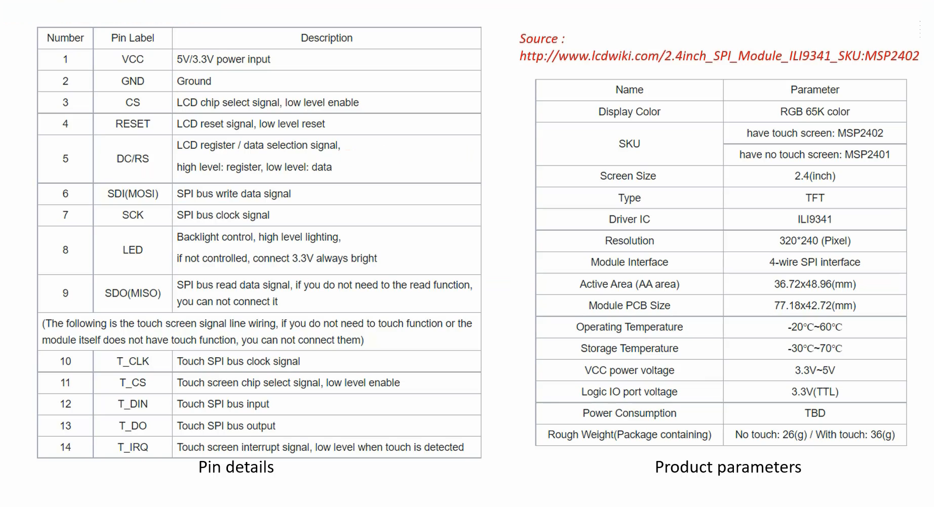
Look at Figure 3, it shows detailed information about the LCD-TFT module. It is based on the ILI9341 chip, and I would recommend selecting the same display module chip. The module uses an LCD driver chip, which operates on SPI communication. The board provides a SPI clock pin, MOSI pin, and MISO pin. Before purchasing this board, please ensure that the Driver IC and interface are SPI and that it supports the Touch screen controller. Additionally, note that the screen size of the module is 2.4 inches.
The connection details are shown in Figure 4. You have to do the connections exactly like this.

Take some jumper wires and establish these connections. Here, PC2, PB13, and PB15 are SPI pins. The SPI2 peripheral of the microcontroller is used to deliver the image contents to the LCD module.
PD9, PD10, and PD11 are some control signals, which I’ll be explaining later. You need not to worry about those lines. Basically, this exercise is just to test the hardware interfacing to ensure all these connections are working fine.
Please note that this LCD module requires 5 Volts of supply, that’s why the ground(GND) and 5 volt points are already there on the Discovery board. So, you can use it.
And also please note that the LED pin of this display should be connected to the 5 Volt. Again, there are multiple 5 Volt points are there on the Discovery board, you can make use of that.
After the connection, you go to the project, first build the project and then run the project.
The roaring tiger demo on the STM32F407-DISC board with external LCD is shown in Figure 5. So, I interfaced the LCD module with the board using some jumper wires.

Get the Full Course on STM32-LTDC, LCD-TFT, LVGL (MCU3) Here.
FastBit Embedded Brain Academy Courses
Click here: https://fastbitlab.com/course1


