About portrait orientation
The orientation of the display refers to how the content is displayed on the screen. The two common orientations are landscape and portrait.
What is Portrait orientation?
Portrait orientation means that the display is taller than it is wide, similar to the orientation of a portrait photograph.
This means that the height of the display is greater than its width. In portrait mode, the content is typically displayed vertically, with the height of the screen determining the vertical resolution and the width determining the horizontal resolution.
In the BSP_LCD_Init function, there is a step where the LCD_config command is used. Specifically, the command used is the ILI9341_MAC (Memory Access Control) register, which is responsible for changing the screen orientation.
Currently, the register is set to landscape mode. Let me explain how to modify the parameters of this command to achieve the portrait mode.
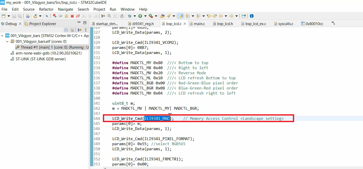
You use the Memory access control values which are mentioned at the beginning of the file( as shown below).
#include "bsp_lcd.h"

#define MADCTL_MY 0x80   ///< Bottom to top
#define MADCTL_MX 0x40   ///< Right to left
#define MADCTL_MV 0x20   ///< Reverse Mode
#define MADCTL_ML 0x10   ///< LCD refresh Bottom to top
#define MADCTL_RGB 0x00  ///< Red-Green-Blue pixel order
#define MADCTL_BGR 0x08  ///< Blue-Green-Red pixel order
#define MADCTL_MH 0x04   ///< LCD refresh right to left
Memory access control(36h) bits degining
If you want to understand more about that command, you can just go to the LCD datasheet and just search for 36h. That’s a command 36h. Here it is, Memory Access Control, as shown in Figure 2.
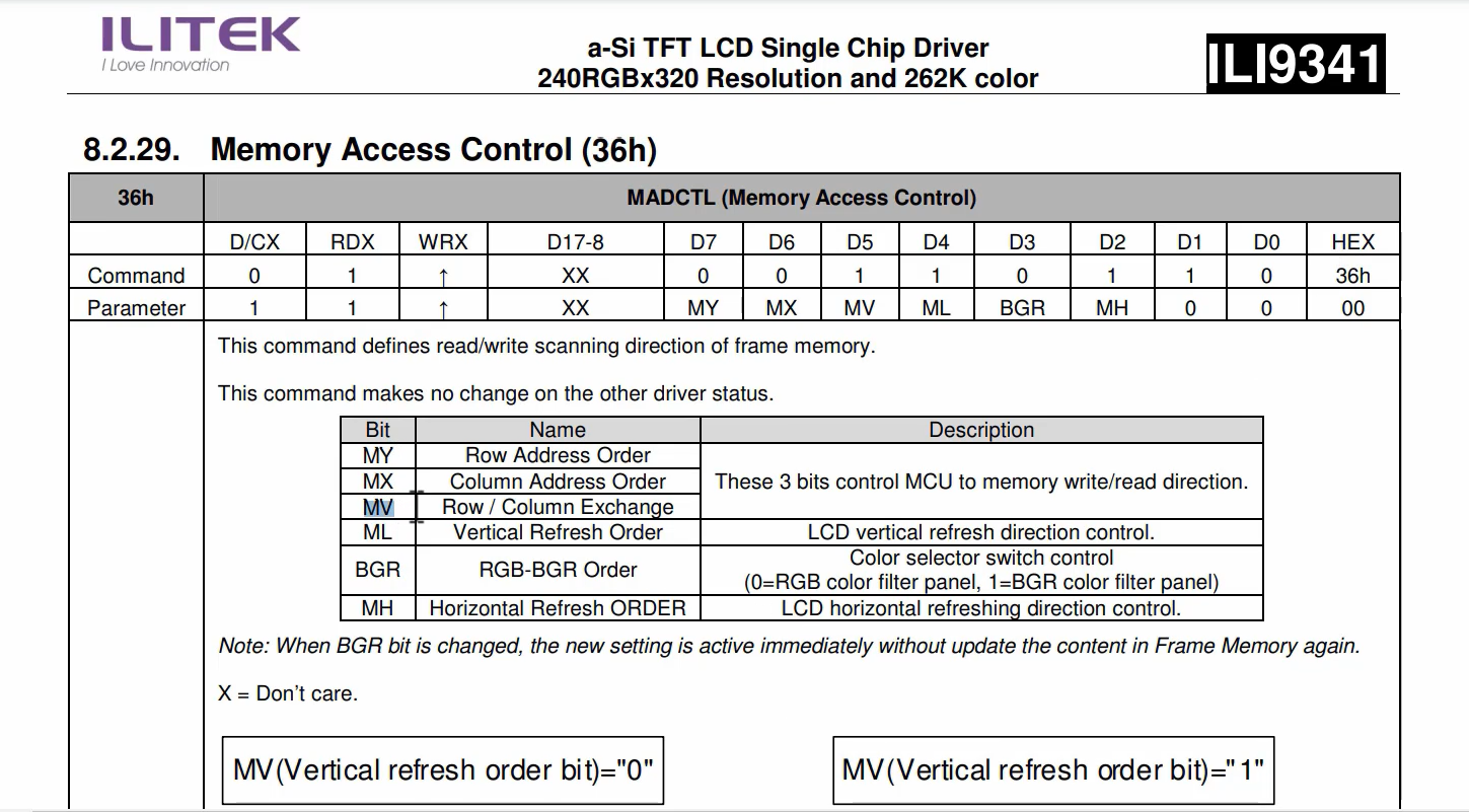
You have to change MY, MX, MV, ML, BGR, and MH bits to get the desired orientation.
How does it work?
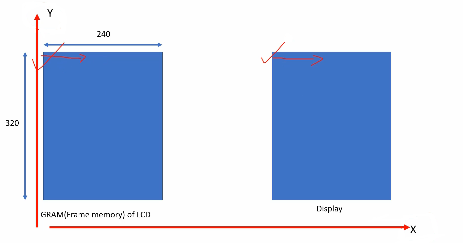
Look at Figure 3. This is your LCD’s GRAM or frame memory. It has a width of 240 pixels and a height of 320 lines. Additionally, there is a display panel.
Whenever you send data to the display module, the data is first stored in the GRAM of the display. Therefore, when you write data to the GRAM in the X direction, it will be displayed in the corresponding X direction on the display panel. This is the default behavior.
But we want something different. What we want is, let’s take the case of the landscape. In landscape, whenever you send data to the frame memory, frame memory will be written in the X direction, but you want the display to be happening in the Y direction. That is a landscape mode, as shown in Figure 4.
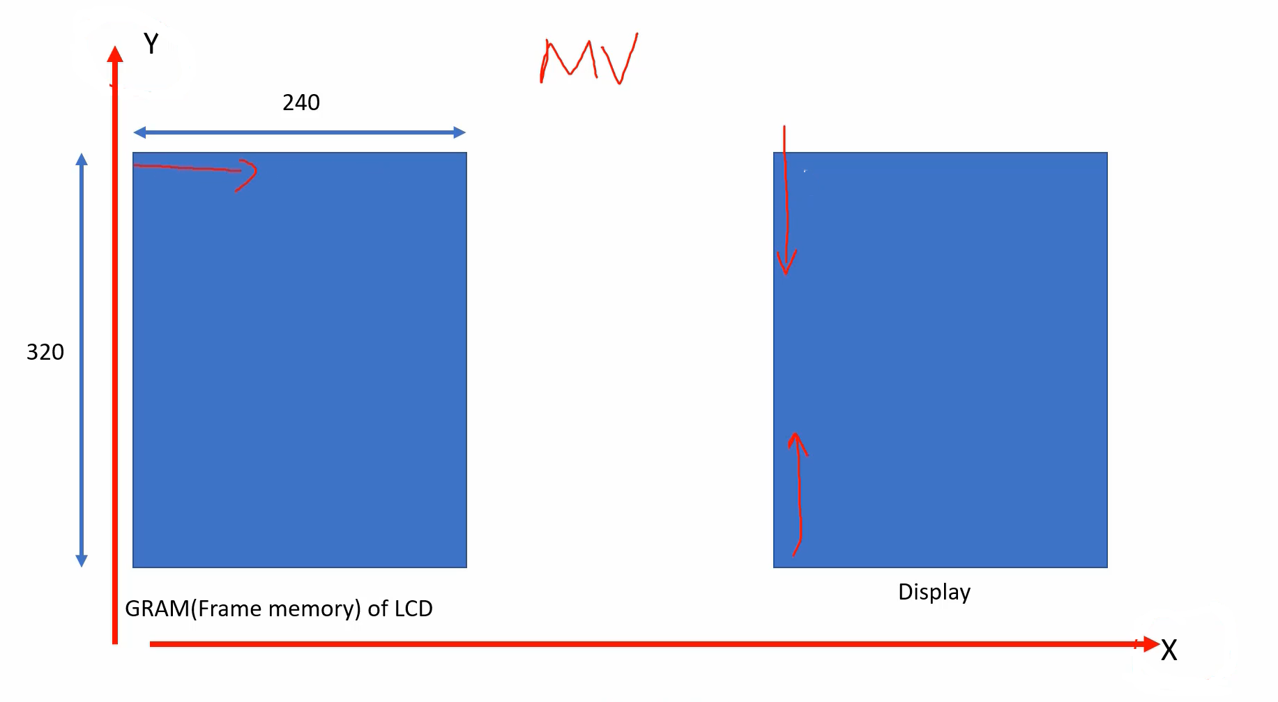
You want the display to happen either in a positive Y direction or in a negative Y direction. This is also a landscape mode. That’s why there is one bit called MV. So, that is used for this XY exchange.
The writing is happening in the X direction, but the display is happening in the Y direction. If you want to achieve that, then you have to set this bit MV = 1, Row/Column Exchange(Figure 2).
If you want to explore more, then go to page number 209, as shown in Figure 5. Here ‘B’ means begin. ‘E’ means end.
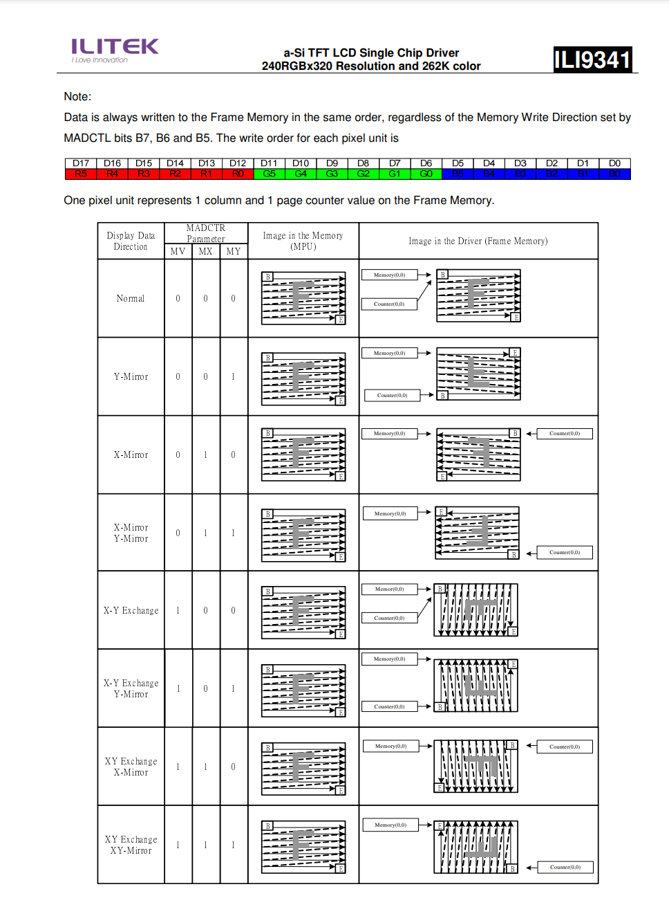
Everything is explained in the below diagram you can see here(Figure 6).
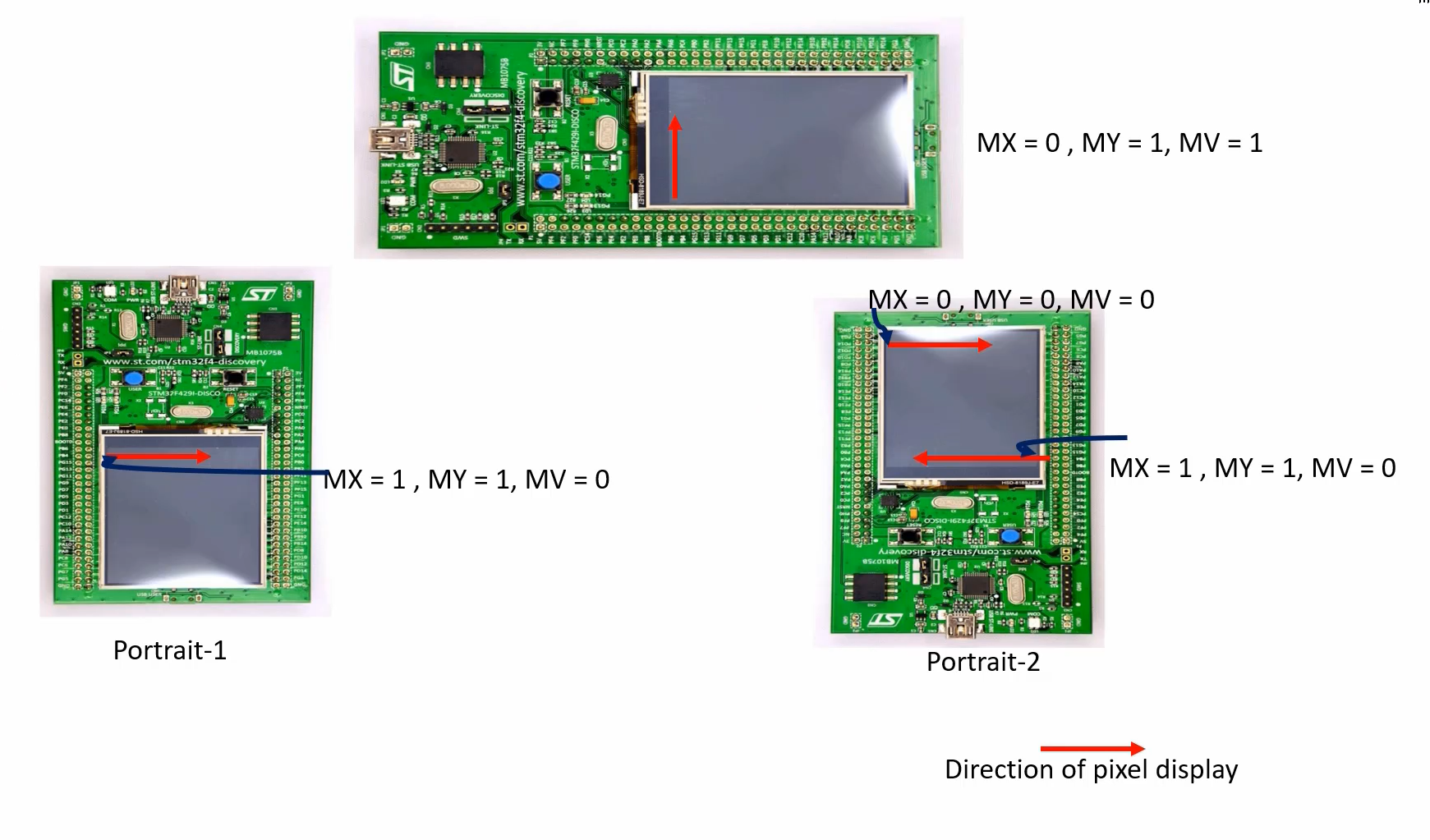
In our portrait-1 mode, we want MX = 1, MY = 1, MV = 0. But, if you want to hold the board in Portrait-2 orientation, then you can use MX=0, MY=0, MV=0 parameters, like that.
There are two more important commands which you need to change. Now you have to change the number of rows and a number of columns information. When it is in the landscape, there are 320 columns. The number of columns we program in this column address set register(CASET).
Look at below code snippet, here you can see that, I have programmed 320, which is 320 means in hex it is 0x140. So, I’m sending something like this.
LCD_Write_Cmd(ILI9341_RASET); //page address set
params[0]= 0x00;
params[1]= 0x00;
params[2]= 0x00;
params[3]= 0xf0; //240 rows = 0xf0
LCD_Write_Data(params, 4);

LCD_Write_Cmd(ILI9341_CASET);
params[0]= 0x00;
params[1]= 0x00;
params[2]= 0x01;
params[3]= 0x40; //320 columns = 0x140
LCD_Write_Data(params, 4);
If you want portrait orientation, this needs to be modified. If you want to change the orientation because in portrait there are 240 columns. So, you have to exchange these values.
Similarly for RASET, that is the page address set, where you need to configure the number of rows.
void BSP_LCD_Set_Orientation(int orientation)
{
   uint8_t params[4];

     if(orientation == LANDSCAPE){

           LCD_Write_Cmd(ILI9341_RASET); //page address set
           params[0]= 0x00;
           params[1]= 0x00;
           params[2]= 0x00;
           params[3]= 0xf0; //240 rows = 0xf0
           LCD_Write_Data(params, 4);

           LCD_Write_Cmd(ILI9341_CASET);
           params[0]= 0x00;
           params[1]= 0x00;
           params[2]= 0x01;
           params[3]= 0x40; //320 columns = 0x140
           LCD_Write_Data(params, 4);

           params[0] = MADCTL_MV | MADCTL_MY | MADCTL_BGR; /*Memory Access Control <Landscape setting>*/
    }else if(orientation == PORTRAIT){

           LCD_Write_Cmd(ILI9341_RASET); //page address set
           params[0]= 0x00;
           params[1]= 0x00;
           params[2]= 0x01;
           params[3]= 0x40; //320 rows = 0x140
           LCD_Write_Data(params, 4);

           LCD_Write_Cmd(ILI9341_CASET);
           params[0]= 0x00;
           params[1]= 0x00;
           params[2]= 0x00;
           params[3]= 0xf0; //240 columns = 0xf0
           LCD_Write_Data(params, 4);

           params[0] = MADCTL_MY| MADCTL_MX| MADCTL_BGR; /* Memory Access Control <portrait setting> */
}
Here, in this file, I have added a new function called BSP_LCD_Set_Orientation. This function allows you to specify the desired orientation. If you choose a landscape, we will reconfigure the RASET and CASET commands and set the MV and MY bits accordingly. On the other hand, if you choose a portrait, we will reconfigure RASET and CASET, modify the memory access control settings, and resend the command with the specified parameter.
To complete this implementation, we need to provide the prototype of this function in bsp_lcd.h.
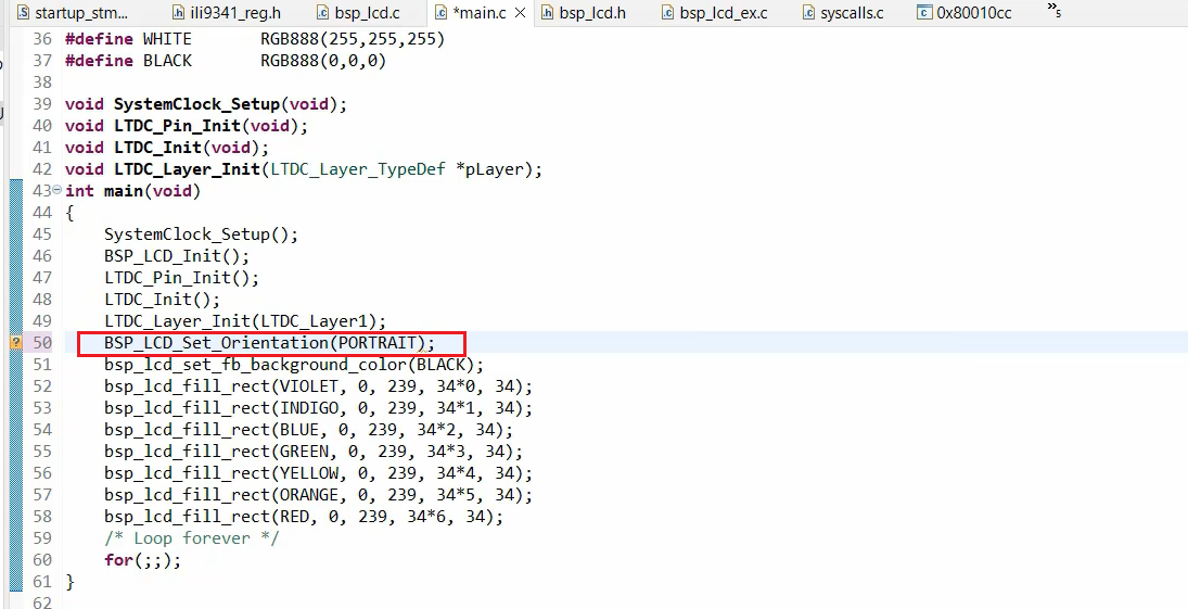
After that, let’s go to the main. And from the main, after you do the Layer_Init, we’ll call the BSP_LCD_Set_Orientation function. Orientation: let’s use Portrait. So, you can also use this after this LCD_Init. And in the bsp_lcd.h, so make sure that you select a Portrait.
In the following article, we will test this.
It’s important to consult the datasheet or documentation provided by the manufacturer of your TFT-LCD display for specific guidance on interfacing and programming in portrait orientation. The details may vary depending on the display controller and module you are using.
FastBit Embedded Brain Academy Courses
https://fastbitlab.com/course1