UART Receiver
During a UART reception, the data shifts in least-significant bit through their RX pin to the receive data register via the shift register, as shown in Figure 1. The heart of the receiver is the receive shift register, where the serial sequence is converted to a parallel word.
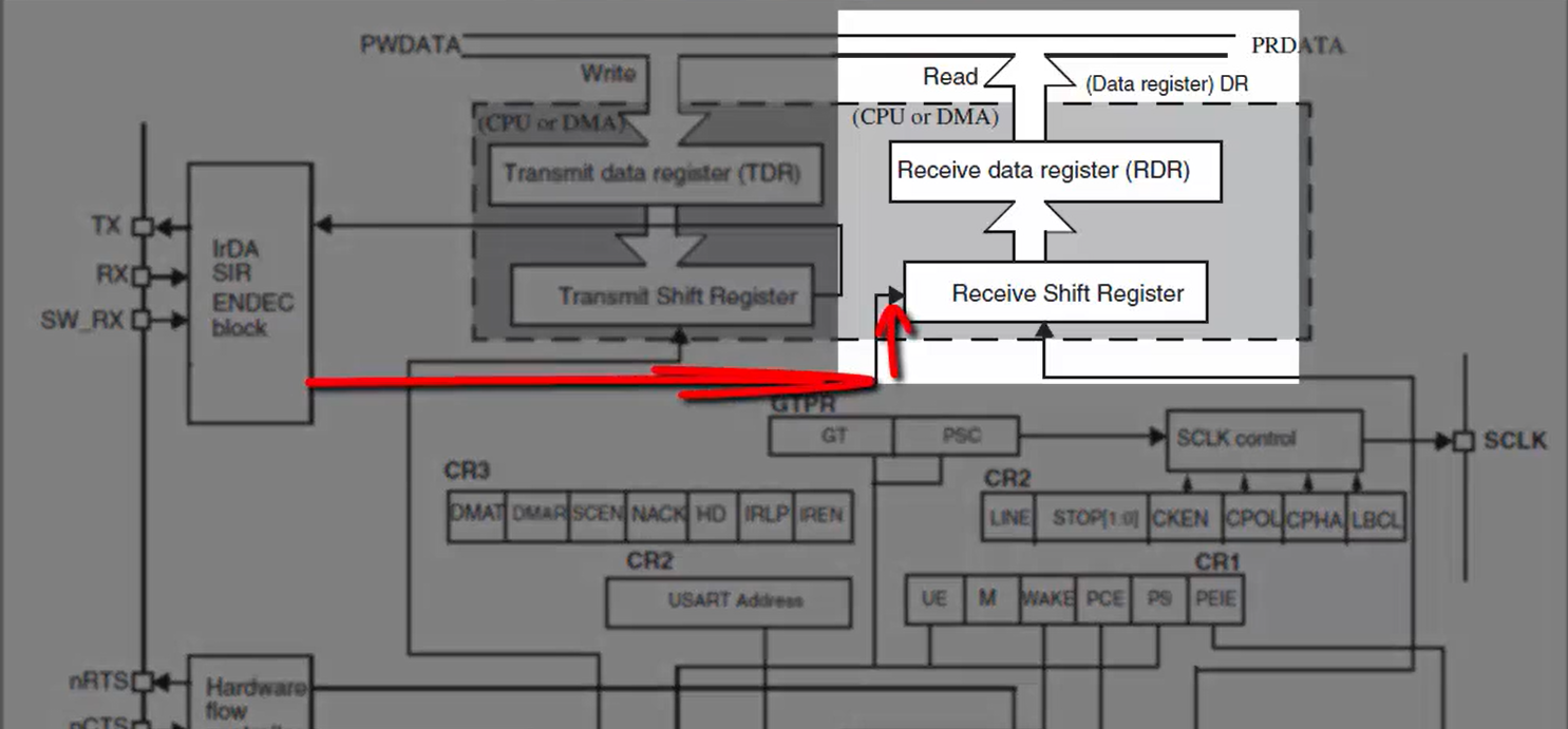
After sampling the RX pin for the STOP bit, the received data bits in the shift register are transferred to the receive data register or RDR.
Steps for UART data reception:
1. Program the M bit in the USART_CR1 to define the word length. Both transmitter and receiver must agree upon this word length.
2. Program the number of STOP bits in the USART_CR2 register.
3. Select the desired baud rate using the USART_BRR register. The baud rate of your transmitter and receiver must be the same.
4. Enable the USART by writing the UE bit in USART_CR1 register to 1.
5. Set the RE bit in the USART_CR1 register, which enables the receiver block of the USART peripheral. Once the receiver block is enabled, it starts searching for the START bit.
6. When the character is received, wait until the RXNE bit is set. If the RXNE bit is set, it indicates that the shift register’s content is transferred to the read data register. In other words, the data has been received and can be read by the software. Instead of polling on the RXNE flag, you can also get an interrupt whenever the RXNE flag is set. For that, you have to enable the RXNEIE control bit in the control register.
7. Clearing the RXNE bit is performed by the software read to the USART data register. The RXNE bit must be cleared by reading the data register before the end of the reception of the next character to avoid an overrun error.
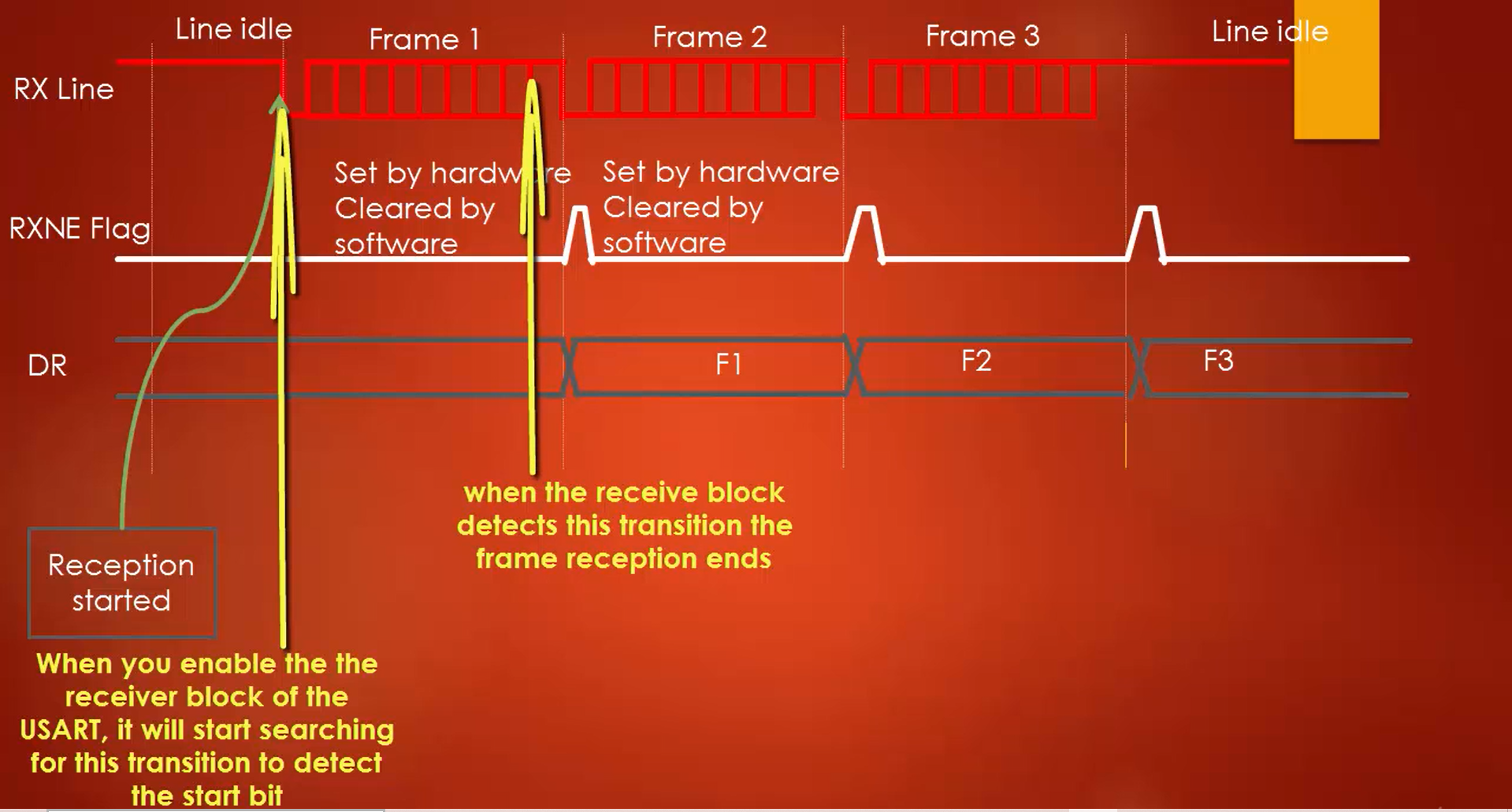
The timing diagram in Figure 2 shows how typically the reception takes place. When you enable the receiver block of the USART by enabling RE bit in the control register, the receiver engine starts sampling the RX pin to detect the START bit. When it detects the START bit, the reception begins, and when it detects the STOP bit, the reception of one frame completes.
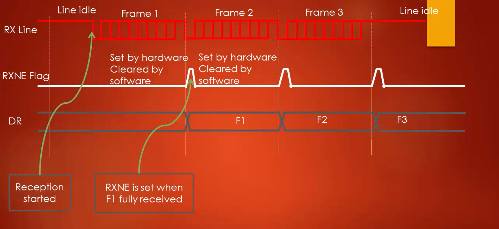
After that, the data in the shift register will be loaded to read the data register (Figure 3), and the RXNE flag will be set. When the RXNE flag is set, it is sure that data is ready to read from the data register.
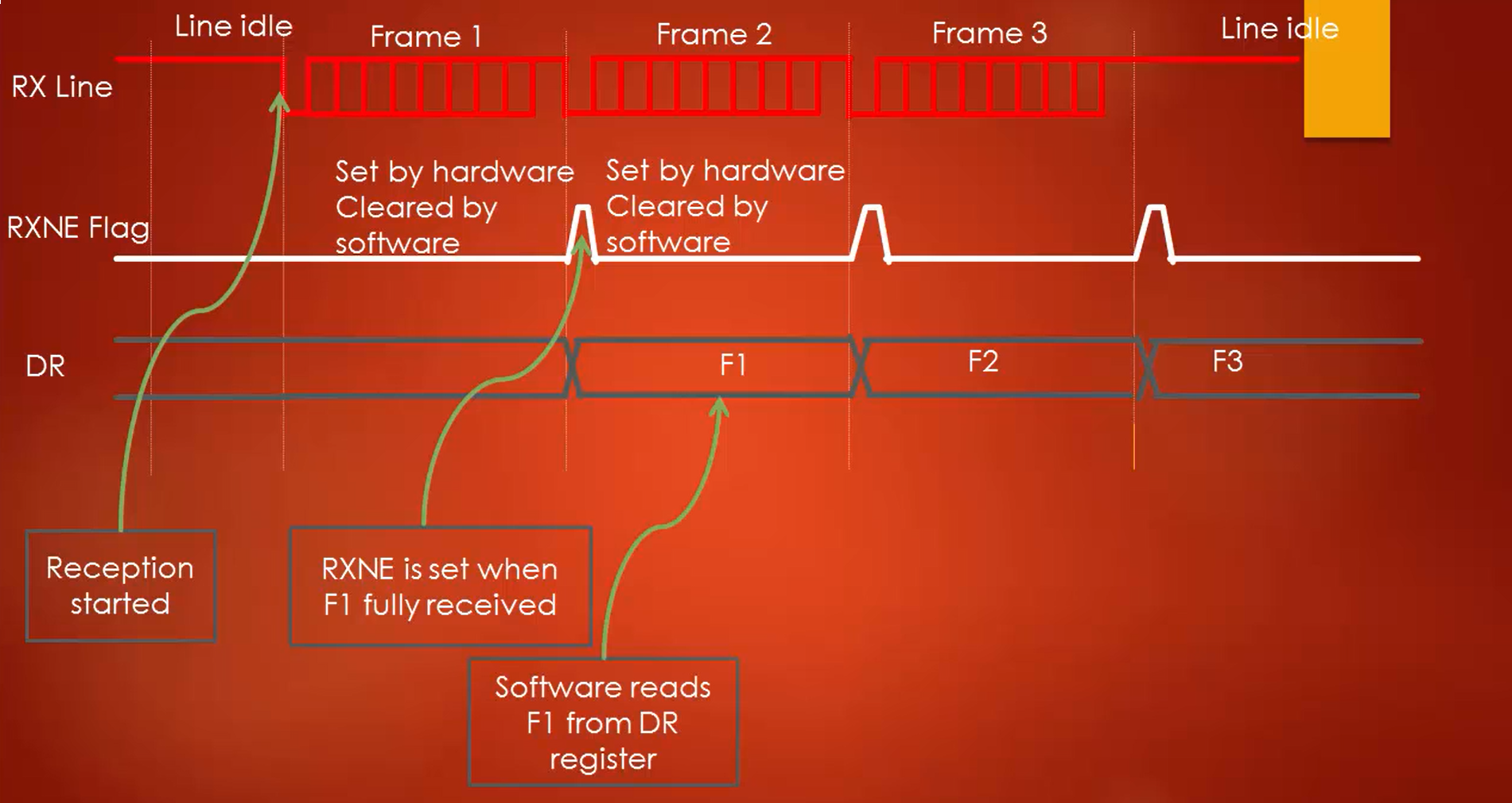
The software can then read out the data register (Figure 4), which also clears out the RXNE flag that was set.
Like that, for every complete frame reception, the RXNE flag will be set, and firmware has to read it (Figure 5).
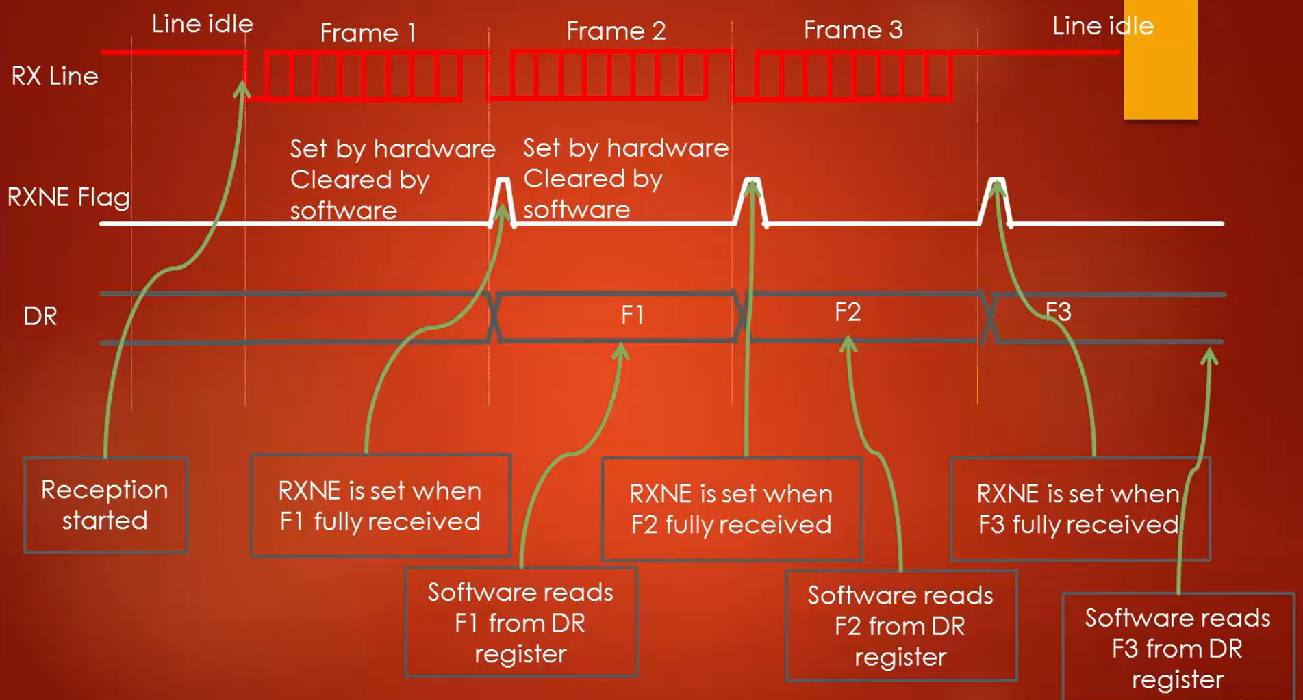
When there is no more data, the line will be held high, which is the idle state of the line (Figure 5). The receiver block of the UART peripheral will keep sampling the RX line to detect the next START bit, even if there is no data on the RX line, which surely consumes power. Therefore, after you are done with RXing of data, it’s always better to turn off the receiver block as per your need if you want to save some power.
FastBit Embedded Brain Academy Courses
Click here: https://fastbitlab.com/course1