USART driver development configurable items
In this article, let’s discuss USART driver development. Before developing the driver, you must know what are the USART peripherals that you have.
In Figure 1, you can see that the USART1 and USART6 are hanging on the APB2 bus, and USART2, USART3, UART4, and UART5 are hanging on the APB1 bus, which can be confirmed by going through the diagram in Figure 1.

Steps for USART driver development (Figure 2):
1. Develop USART driver.c and driver.h files.

2. Remember that you have to update the device-specific header file (Stm32f407xx.h) with the details regarding the USART peripheral.
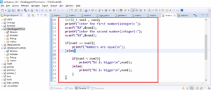
3. After that, you can write some sample applications to test the driver.
Driver API requirements and user configurable items:
The user-configurable items (Figure 3) for the application are as follows:
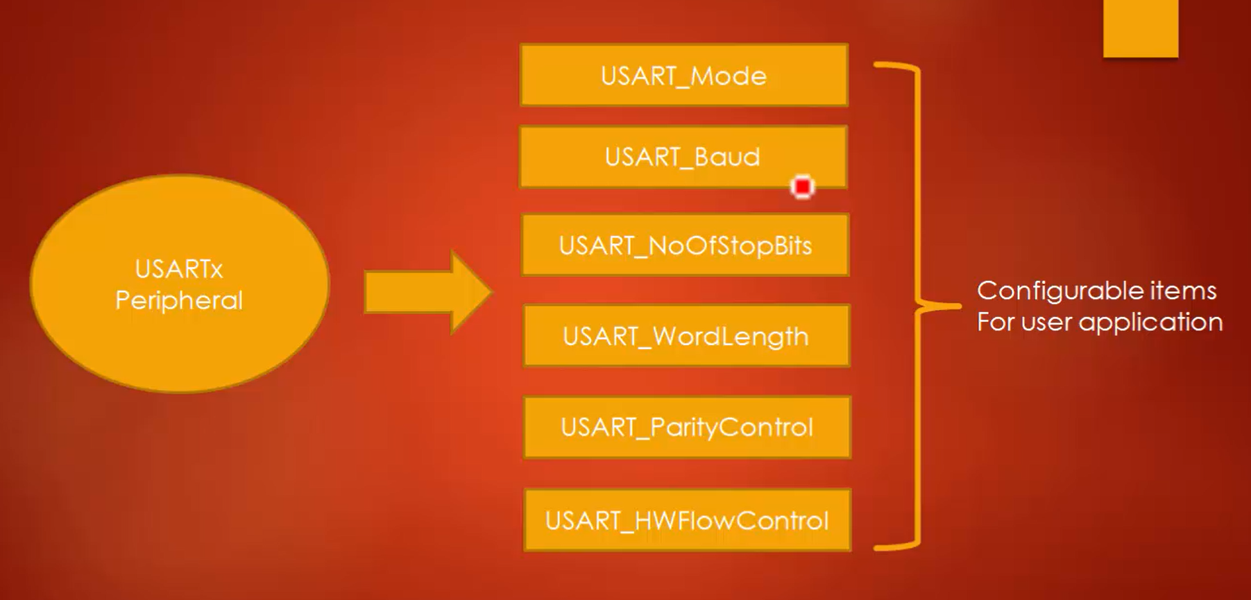
- USART_Mode: In USART, it can be in transmit mode, receive mode or both in transmit and receive mode.
- USART_Baud: This configurable item is used to mention the baud rate.
- USART_NoOfStopBits: It is used to configure the number of STOP bits.
- USART_WordLength: You can configure the word length by using this configurable item. There are only two choices for word length, either 8 bits or 9 bits.
- USART_ParityControl: By using this configurable item, you can configure whether the parity bit must be included in the USART frame or not. The parity can be no parity, even parity or odd parity, which can be mentioned here.
- USART_HWFlowControl: The hardware flow control details can be mentioned in the hardware flow control user-configurable item.
The above are the configurable items given to the application to configure the USART peripheral.
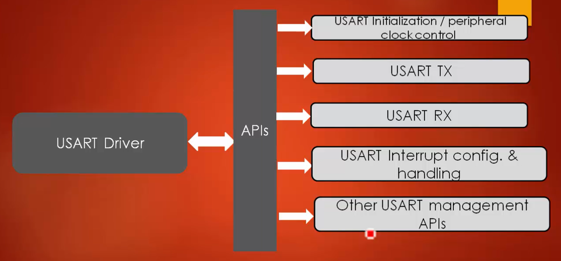
The list of APIs that we are going to develop in this section are as follows (Figure 4):
- USART initialization/ peripheral clock control.
- USART TX
- USART RX
- USART interrupt configuration and USART interrupt handling APIs.
- Other USART management APIs.
The procedure of developing APIs are exactly similar to the I2C and SPI.
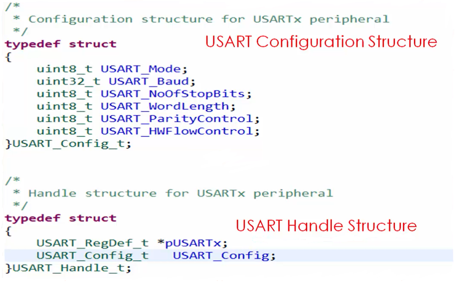
USART handle structure and configuration structure:
The configuration structure and handle structure for USART communication are as shown in Figure 5.
You have to create one member element in the USART_Config_t structure for all the configuration items and then create the handle structure in the USART driver file.
Exercises to be completed before coding the driver:
- Create a USART driver header file and source file in the driver directory.
- Include complete USART register definition structure and other macros such as peripheral base addresses, Device definition, clock enable, clock disable, etc. in MCU specific header file.
- Also, add USART register bit definition macros in MCU specific header file.
- Add USART configuration structure, and USART handle structure in USART header file.
In the following article, let’s see USART driver APIs prototypes.
FastBit Embedded Brain Academy Courses
Click here: https://fastbitlab.com/course1