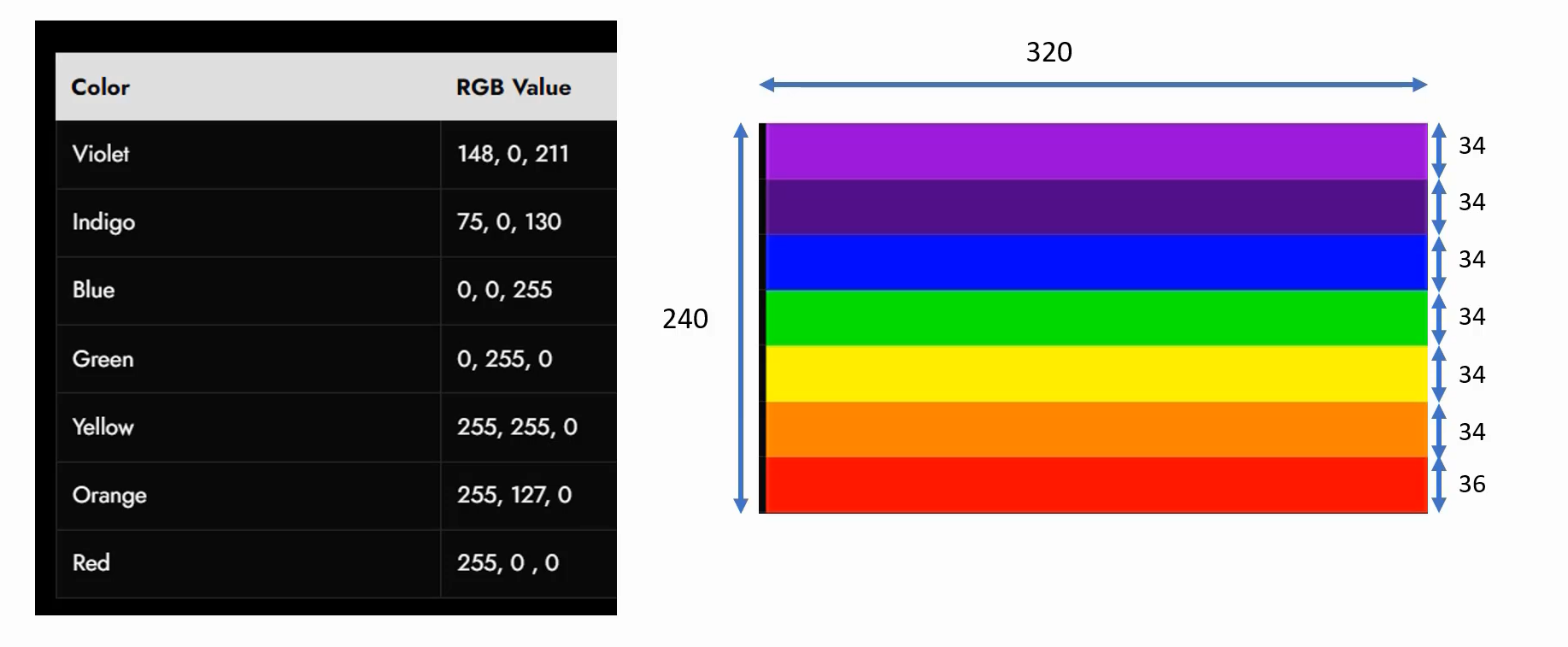
Displaying VIGBYOR bars on the display
Exercise: Display VIBGYOR color bars
Here we code from scratch. We will not be using the STM32Cube code auto-generation feature, and for later exercises, we can use the code auto-generation feature. But for this exercise at least we will code everything from scratch and when we code everything from scratch, we will learn a lot of concepts and we can debug our projects better. And we’ll also learn a lot of internal things about the peripherals and how things are working.
Here we are using the STM32F429IDISCOVERY board for this exercise.
Steps
1. Create a new project for your microcontroller or board using STM32CubeIDE
2. Setup the main system clock
3. Setup AHB and APB clocks
4. Setup the pixel clock(DOTCLK)(Not required for STM32F407x-DISC1 board with external LCD)
Because the DOTCLK or pixel clock is part of the RGB interface. So, we are not using the RGB interface for this combination. That’s why this step is not required.
5. Configure the SPI peripheral.(Not required for STM32F746-DISC board)
Because, we are not going to initialize the LCD module, which is there on the STM32F746-DISC board. So, no initialization is required for that LCD module.
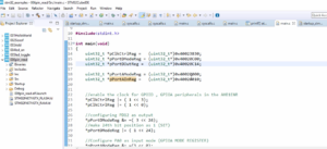
6. Setup the framebuffer in RAM
This is a place where you manipulate the frame buffer with VIBGYOR colors.
7. Initialize the LCD module by sending LCD commands over SPI(Not required for STM32F746-DISC board)
8. Configure and enable the LTDC peripheral(Not required for STM32F407x-DISC1)
Because we are using the DBI interface for this board. That’s why we are not using LTDC here. So, this step is not required for this board.
Once you configure and enable the LTDC peripheral, the LTDC will generate all the synchronization signals, timing signals, and data signals, and you should start seeing the output on the display.
9. Send frame buffer contents to LCD over SPI (Only in the case of STM32F407x-DISC1)
Basically, you have to write one SPI transmit function where you have to send the frame buffer contents using your code.
10. Make sure that all error interrupts are enabled and ISRs implemented
So that we can trap the code if something goes wrong.
Create a new project for your microcontroller or board using STM32CubeIDE
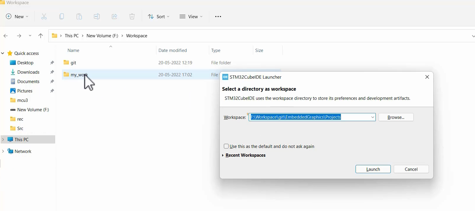
First open STM32CubeIDE.
It shows STM32CubeIDE Launcher. Here you select a directory as a workspace. Just browse the folder path where your project should store, or copy and paste the path here, and then click Launch.
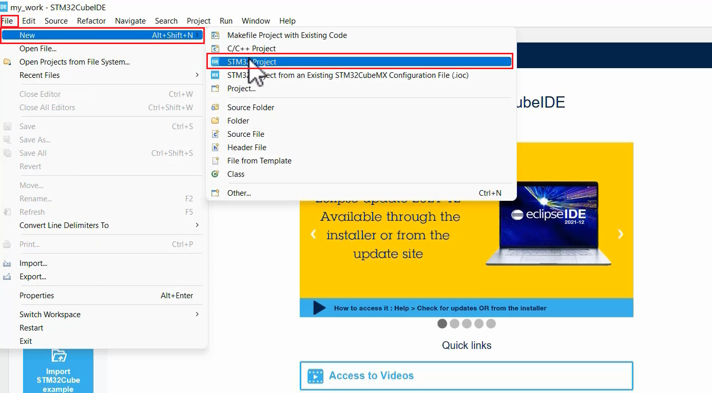
Now let’s create a new project.
From the menu bar, select File -> New -> STM32 Project, as shown in Figure 3.
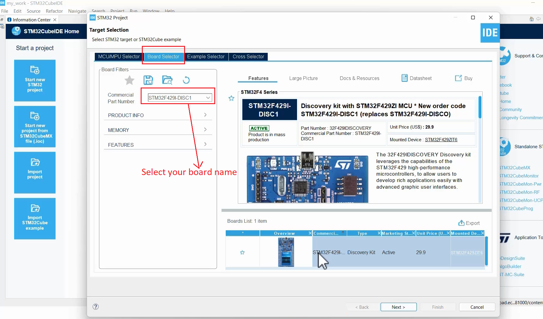
Then, click on the Board selector, and type or select your board name. Here mine is the STM32F429 Discovery board. I selected that board. And click Next.
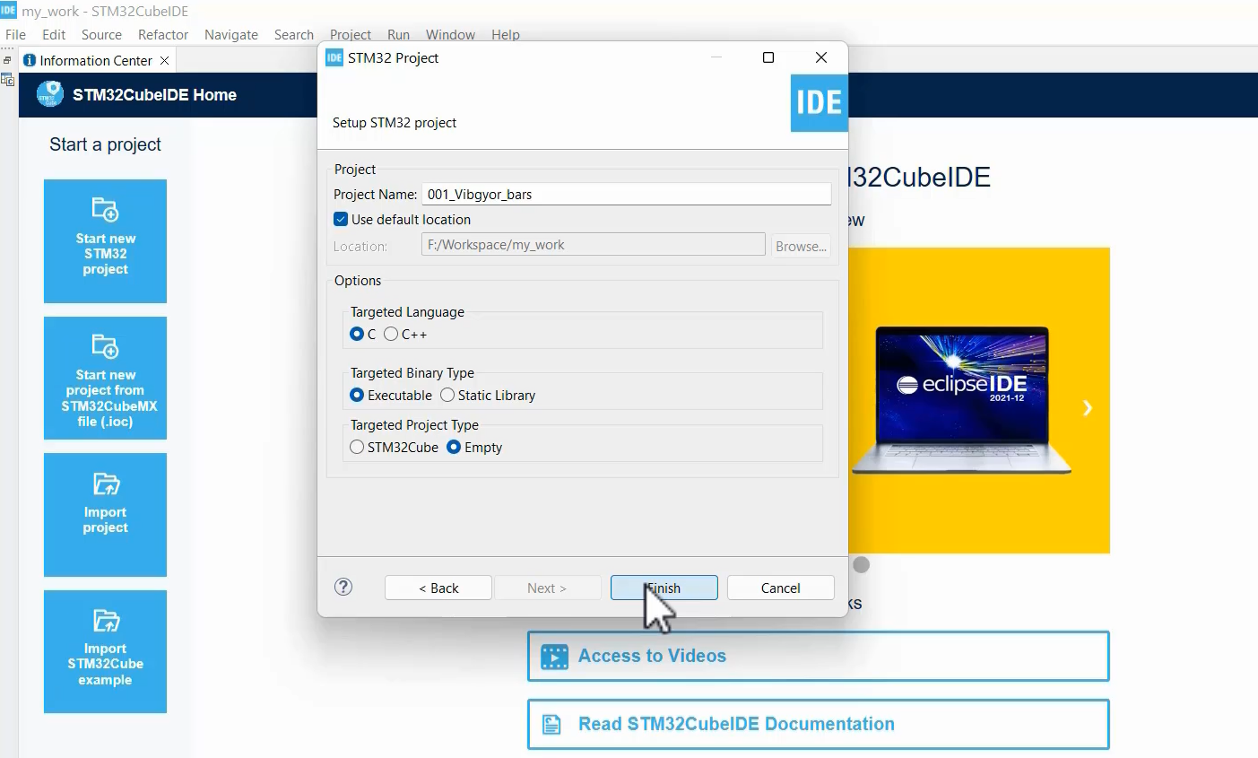
Here give your project name, and targeted language select C, targeted Binary type select Executable, and targeted project type select Empty. Because we are not using STM32Cube code auto-generation. And then click Finish.
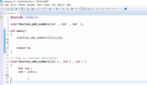
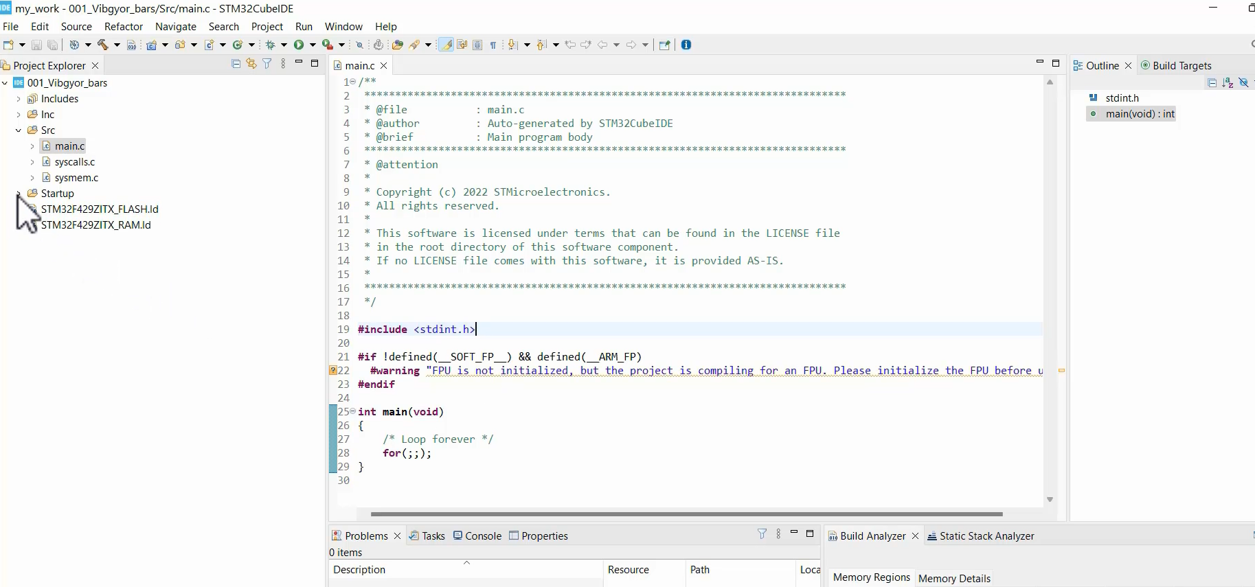
This project creation adds some minimal files like the main.c, which doesn’t have any code, so it just contains the main function.
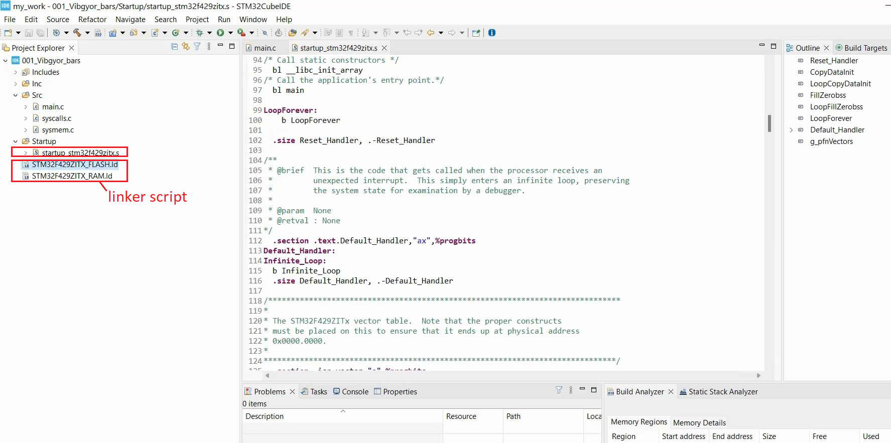
And it adds two important files here(Figure 7). A ‘startup‘ file and some ‘linker script‘.
That’s how you create a new project.
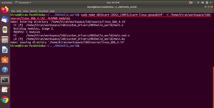
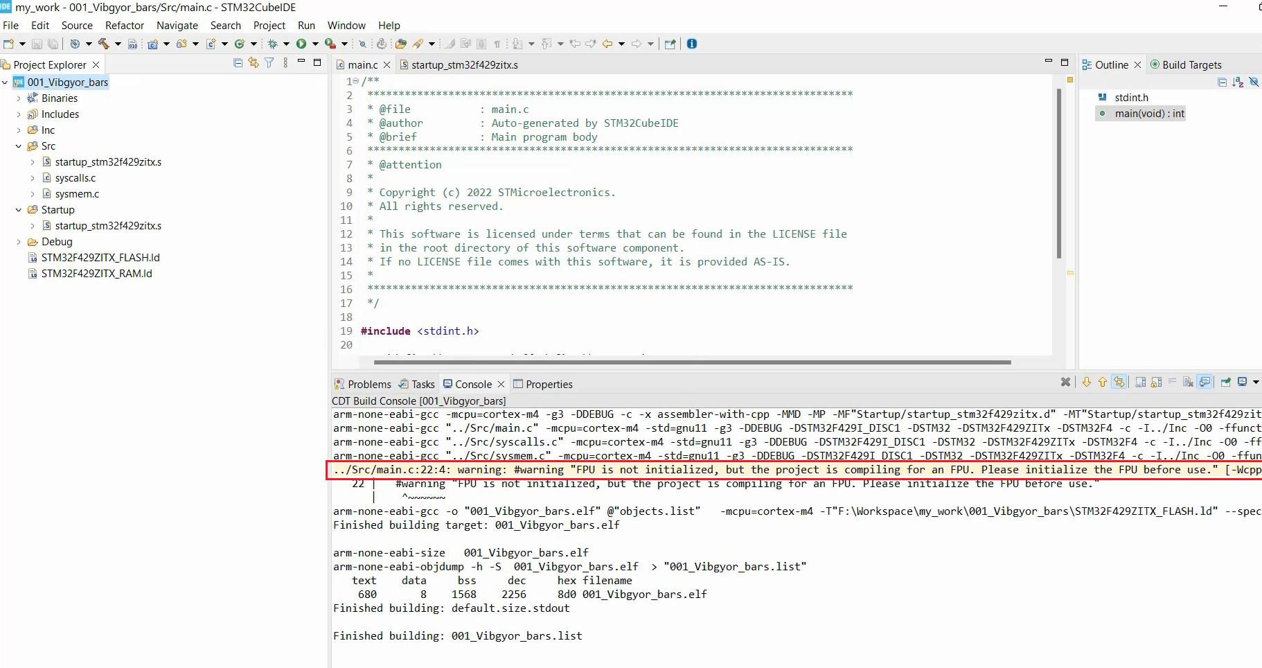
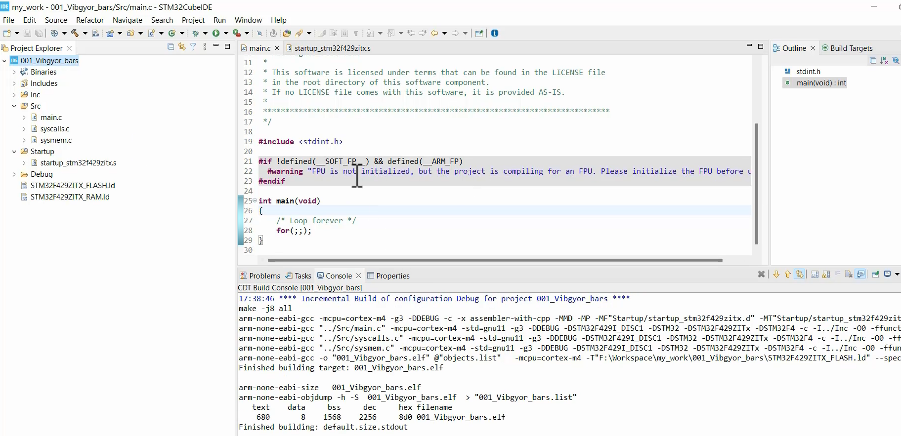
When you build this project, it says that “the FPU is not initialized, but the project is compiling for an FPU”, as shown in Figure 8.
Basically, what IDE is saying is, the project uses hardware floating point, but it is not initialized in the code. So, it may generate some faults.
For a time being, I will go to the settings of the project. Go to Build > Settings > MCU settings> and here in the Floating-point unit it is selected as Hardware implementation. So, if you use the hardware implementation, then you have to initialize it, but that is not done in the code. So, we will use Floating point ABI as a Software implementation. Then click Apply, and Apply and Close, as shown in Figure 9.
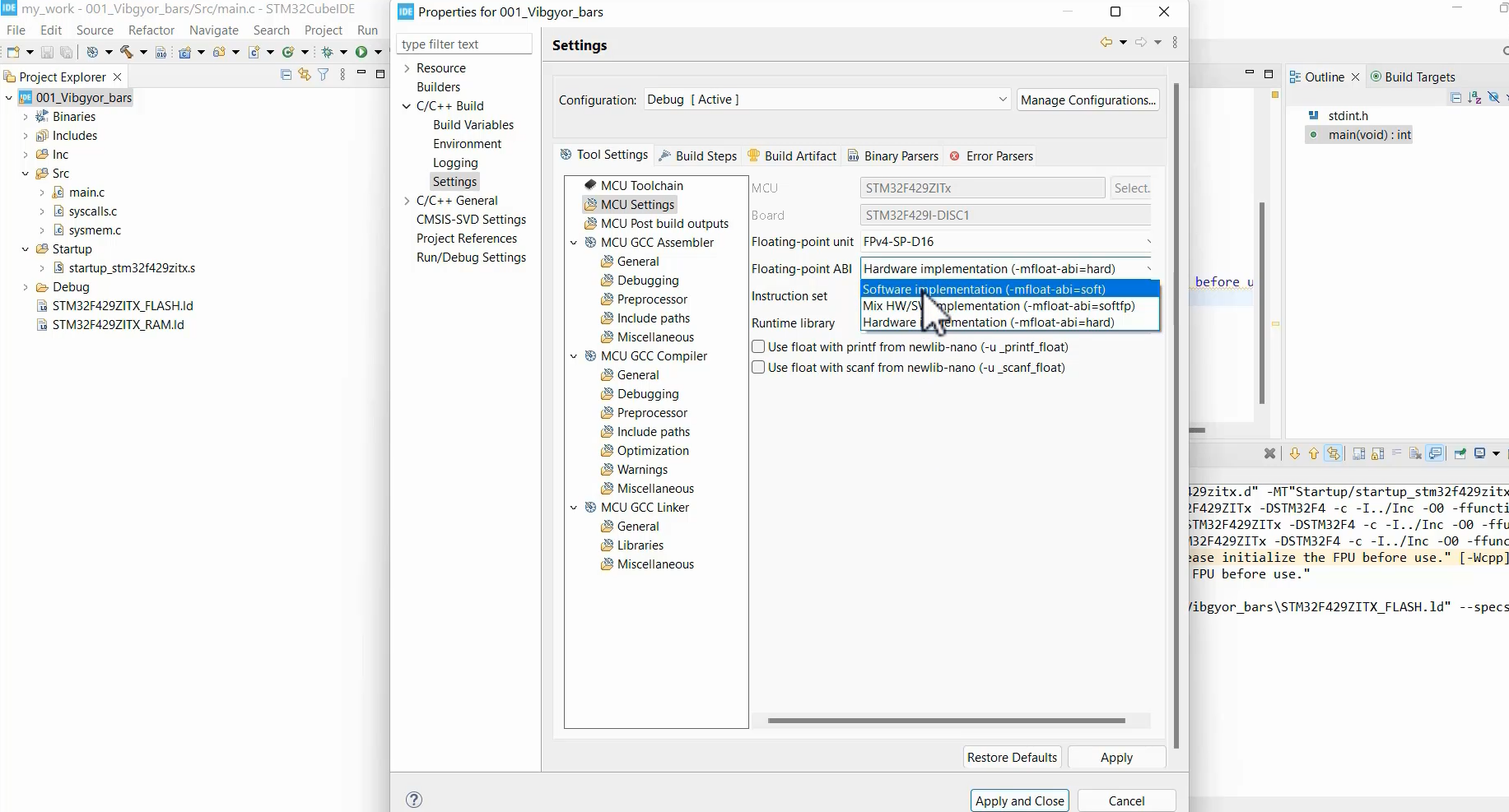
After building this project, that warning disappeared.
We created the first step. In the following article, let’s set up the main system clock.
Get the Full Course on STM32-LTDC, LCD TFT, LVGL (MCU3) Here.
FastBit Embedded Brain Academy Courses
Click here: https://fastbitlab.com/course1