Coding to Turn on an LED
Exercise:
Write a program to turn on the LED of your target board.
For this exercise, we need the knowledge of
- pointers
- bitwise operators
- Hardware connections
Hardware connections
- Let’s understand how external hardware(LED) is connected to the microcontroller.
- For this, we have to refer to the schematic of the board you are using.
Let’s go to ST’s documentation’s resource section, download the schematic, and then analyze it.
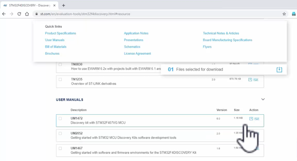
Let’s refer to the online documentation of the STM32F4DISCOVERY board, which is there on the ST’s website.
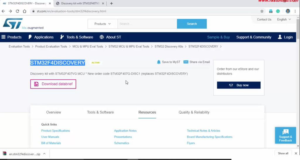
Here, we have the schematic, as shown in Figure 1. Let’s download this.
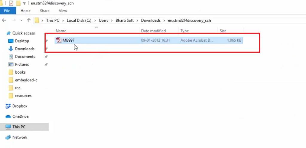
You get the PDF file when you download this, as shown in Figure 2. Open that pdf file.
In the schematic, you can search for the LEDs. If you browse the document, you find LEDs, as shown in Figure 3.
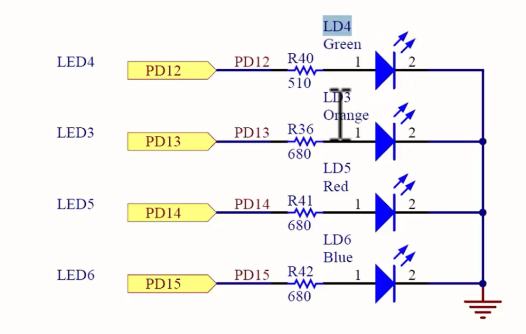
Here you can see that this board has 4 LEDs. The part number of the Green LED is LD4, the part number of the Orange LED is LD3, and so on. On the board, you can identify the LEDs by these names. So, these are the part numbers that should be mentioned on the board as well.
For that, you have to go to the user manual, as shown in Figure 4. Let’s open the user manual.
In the user manual, you can see that they have explained the board.
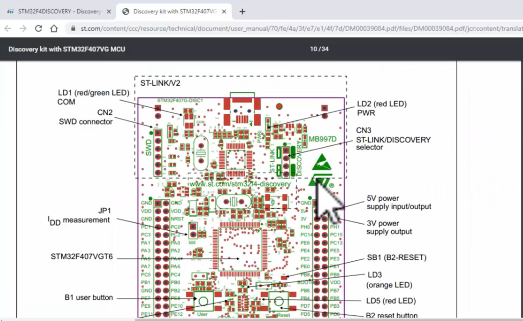
Let’s zoom on the board. You can see that LD4, LD5, LD6, these are the LEDs. So, they have a mention here. Just explore this figure in the user manual.
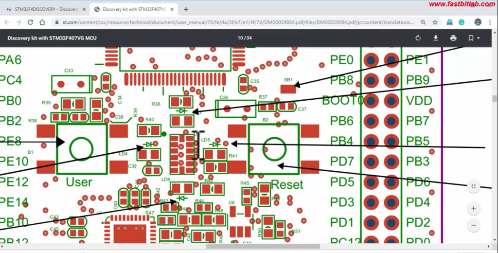
Figure 3 shows how the LEDs are connected to the microcontroller pin. The Green LED is connected to the pin PD12; PD12 means Port D PIN number 12. And the LED Blue is connected to PD15, that is, Port D PIN number 15. That leads to our next discussion.
Ports
STM32F407VGT6 Microcontroller has many ports, and we can identify all these ports by going through the schematic again.
If you go to the schematic, there is a picture of the microcontroller. U4A is a part number of the microcontroller, and the microcontroller is STM32F407VGT6. And it has many pins, but on this board, all these pins are exposed.
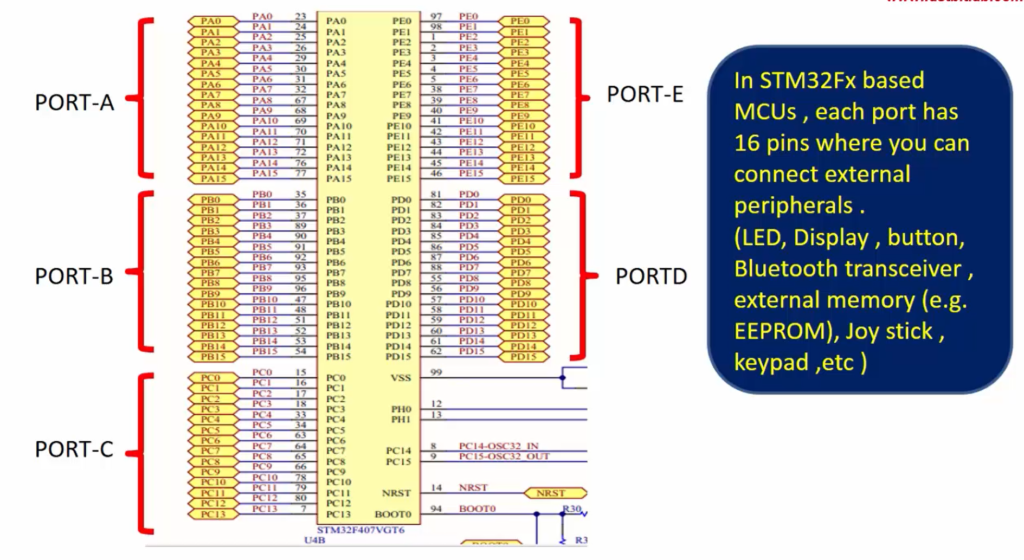
In STM32Fx based MCUs, each port has 16 pins where you can connect external peripherals such as LED, Display, button, Bluetooth transceiver, external memory(e.g.EEPROM), Joystick, keypad, etc.
If you want to do those external connections, you can take help from these ports, which are exposed on the board. So, if you look into this picture, all these pins can be segregated into different ports like Port-A, Port-E, Port-D, and each port is a collection of 16 pins.
For example, all these PA0 to PA15 pins belong to Port A. The first pin is called PA0(that is Port A PIN number 0), and the last pin here is PA15. And 23, 24, 25, and so on are the PIN numbers of the microcontroller. That means, the microcontroller’s 23 pin is PA0, which is the 0th pin of Port A. It’s like that.
This microcontroller has many ports like Port-F, Port-G, Port-H, etc., but only these ports are exposed on the board.
Now let’s consider LED 4, which is LD4. This LED is connected to PD12 exactly like this, as shown in Figure 8. Here is a microcontroller and Port-D, and at the 12th pin, this LED is connected.
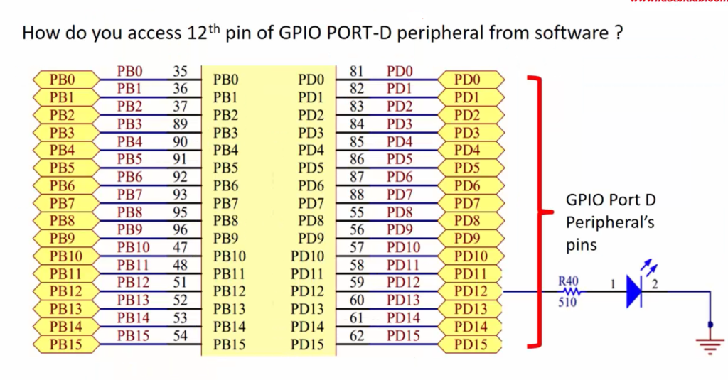
How do you access the 12th pin of GPIO PORT-D?
Port-D is also called GPIO Port D. GPIO stands for General-Purpose Input/Output. PD0 to PD15 are called General-purpose I/Os, because it can be used for any purpose. Like you can use that to connect external peripherals, or you can use that pins to do some other protocol communication like Ethernet communication, UART communication, I2C communication, etc. That’s why these pins are called General-purpose I/Os.
Now you have to think about controlling this PD12 pin. If you control the PD12 pin, you can control the LED. So now the question is, how do you control this pin from the software.
Now your goal is to control the I/O pin PD12’s state, either HIGH or LOW through the software to make LED turn ON or turn OFF, and we are going to learn that. You have to understand how these pins are controlled from the microcontroller, and we understand that in the following article.
FastBit Embedded Brain Academy Courses
Click here: https://fastbitlab.com/course1