Implementation of I2C init API: Part 1
In this article, let’s code I2C_Init. Let’s discuss the things that need to be configured in the I2C registers.
- To control the acking, you need to configure the ACK (10th bit) bit of the CR1 register, as shown in Figure 1.

2. Configure the FREQ field of the CR2 register.
The FREQ bits must be configured with the APB clock frequency value. That means the exact clock frequency of the APB1 bus must be calculated. We already know that in our case, it is 16. But it need not be the same always. The user may change this value. Therefore, it is required to calculate the FREQ field.
Let’s create a small function to calculate the APB1 bus clock’s value, as shown in Figure 2.

Refer to the clock tree shown in Figure 3 to know how the PCLK1 is calculated.
To calculate the PCLK1, First, find out the source by reading the RCC registers. After that, calculate the AHB prescaler and APB1 prescaler.
The value of PCLK1 depends on the clock source, which means the system clock, and it is decided depending on the HSE, HSI, PLLCLK, PLLR, etc. In our case, the system clock is HSI (16MHz), which is then divided by the AHB prescaler to get the AHB clock.
To obtain the APB1 clock, divide the AHB clock by APB1 prescaler, and then the APB1 clock is delivered to the APB1 peripherals where I2C is connected.

In the clock configuration registers of RCC, refer to the bit numbers 2 and 3 (Figure 4).

Calculate the values of bits 2 and 3 to determine which clock source is used as the system clock. Now let’s write the code for finding the clock source.
- Create a clksrc variable of type uint8_t.
- Read the values of bits 3 and 2 of the RCC_CFGR register to the clksrc variable. This is done by using clksrc = (RCC -> CFGR >> 2) statement. Here the right shift by two is done to bring the bit number second and third to the bit position zero and one.
- Mask the first two bits with the bitwise & operator. clksrc = ((RCC -> CFGR >> 2) & 0x3) will mask all other bits except the bit number zero and bit number one, where the value is stored.
- Then select the system clock depending on the value stored in the clksrc variable, as shown in Figure 5.

Find out the value of AHB prescaler. This value is decided by the bit fields 4 to 7 of the RCC_CFGR register, and the field name is HPRE, the AHB prescaler. If the system clock is less than eight, then the system clock is not divided; else, the system clock will be divided according to the information in Figure 6.
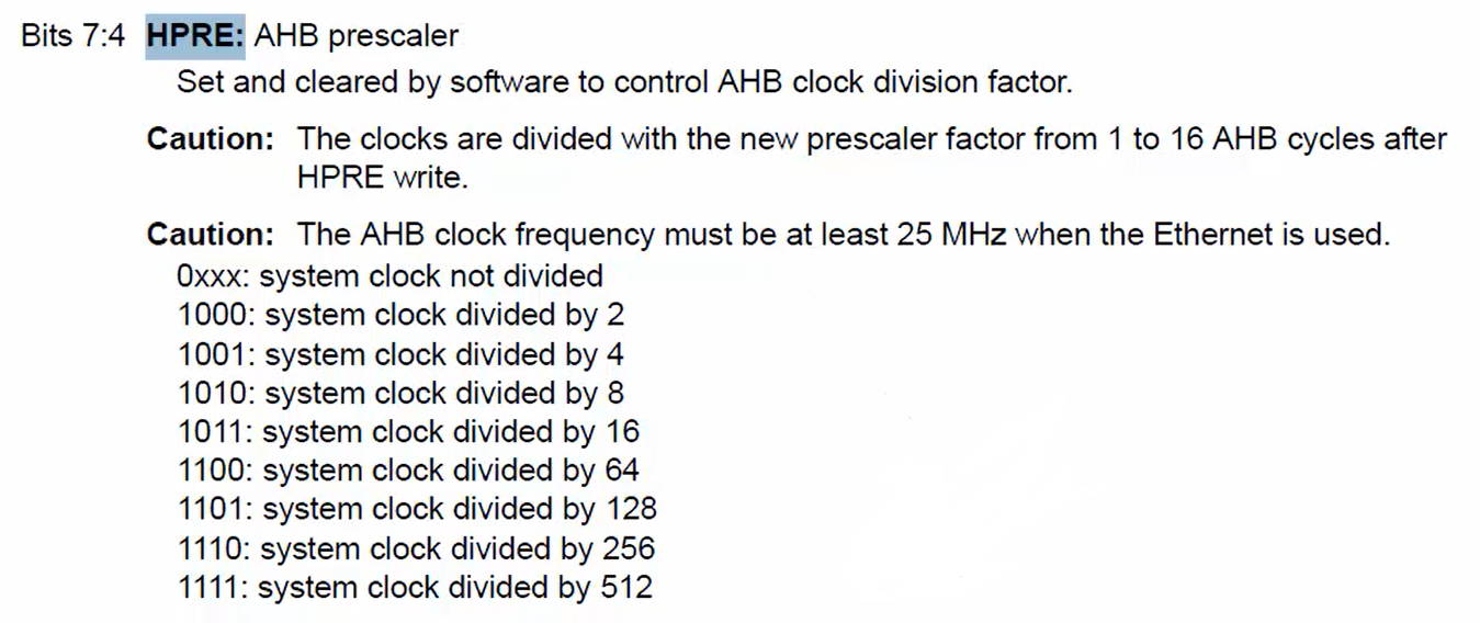
Read the value of HPRE into a temp variable using temp = (RCC -> CFGR >> 4) statement. Then temp = ((RCC -> CFGR >> 4) & 0xF) will mask all other bits except the first four bits. Select the AHB prescaler value from AHB_PreScaler [] array depending on the temp, as shown in Figure 7.
Where AHB_PreScaler is a variable of type array, which holds all the division factors.

We already found out the value of AHB prescaler.
The next task is to find out the APB1 prescaler. For this, you have to refer to the 10, 11, and 12th bit of the RCC_CFGR register shown in Figure 8.
If the PPRE1 field’s value is less than four, then the AHB clock is not divided; otherwise, the AHB clock will be divided according to the division factors in Figure 8.

Read the value of PPRE1 into a temp variable using temp = (RCC -> CFGR >> 10) statement. Then temp = ((RCC -> CFGR >> 10) & 0x7) will mask all other bits except the first three bits.
Select the APB1 prescaler value from APB1_PreScaler [] array depending on the temp value, as shown in Figure 9. Where APB1_PreScaler is a variable of type array, which holds all the division factors for PPRE1.

Finally, the pclk1 can be calculated using pclk1 = (SystemClk / ahbp) / apb1p, and then the pclk1 value is returned (Figure 10).

The program discussed till now is the generic function to calculate the value of PCLK1, and a similar function can be created for PCLK2—here no need to create a PCLK2 function since the I2C is not hanging on other buses. Let’s continue it in the following article.
FastBit Embedded Brain Academy Courses,
Click here: https://fastbitlab.com/course1