Keypad interfacing
In this article, let’s learn about 4×4 matrix keypad interfacing. We interface the 4×4 keypad to our STM32 microcontroller and read the key pressed, and we write the code entirely from scratch.
4×4 Keypad interfacing
If you want to reproduce this project you would need,
- One 4×4 matrix keypad
- Few jumper wires to do the connections.
And you have to write a program which detects and prints the key pressed.
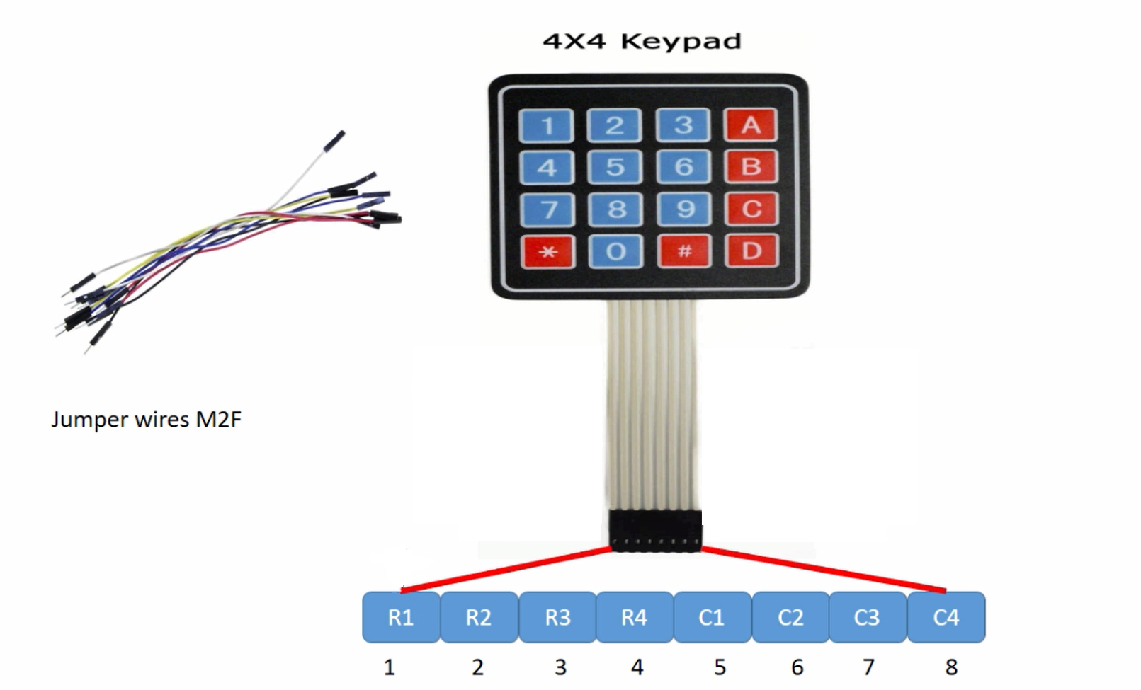
This is a 4×4 matrix keypad or it is also called a hex keypad, as shown in Figure 1. It has got 8 pins to read the key pressed.
And out of eight pins, the first 4 pins are called row pins. R1, R2, R3, and R4 are row pins. And the next 4 pins are called column pins. C1, C2, C3, and C4 are column pins.
You would need a few jumper wires to connect this keypad to the STM32 microcontroller board.
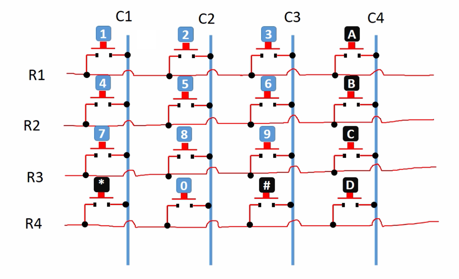
Keypad’s internal connection is shown in Figure 2.
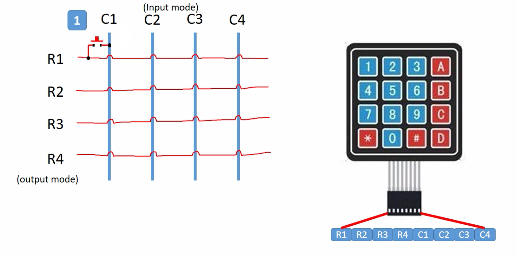
There are 4 column lines and 4-row lines. And in between the row and a column, a key is implemented.
And when no key is pressed on this keypad the columns and rows are completely isolated. So, there is no connection at all.
Please note that columns C1, C2, C3, and C4 are input to the microcontroller. Microcontroller code reads C1, C2, C3, and C4 to detect the key pressed. And the pins R1, R2, R3, and R4 are outputs to the microcontroller.
So, columns are input, rows are output, you should remember that.
Let’s take an example of the first key, which is ‘1’. When you press key ‘1’, row 1 and column 1 come into contact, and you should detect this in your program, and then by some logic you have to decide which key is pressed.
The only thing I want you to understand from this image is, when the key is pressed there will be a contact between a row and a column.
Let’s understand how we can connect a 4×4 keypad to the microcontroller, as shown in Figure 4.
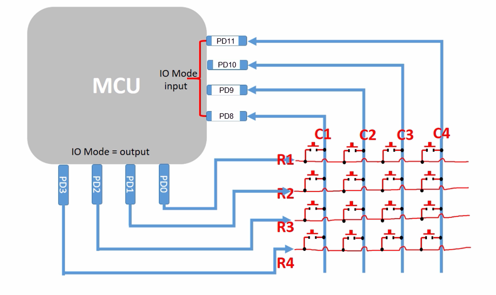
You need 8 IO pins on the microcontroller to do this interfacing.
So, you have to arrange for 8 free IOs on your board. You know how to get the free IO details. You have to go to the user manual of the board and you have to understand what are all the IOs are free, so that you can use them to interface with the keypad.
In this case, column C1, C2, C3, and C4 are connected to PD8, PD9, PD10, and PD11. And your software should keep all these IO pins in input mode.
And all the rows R1, R2, R3, and R4 are connected to the 4 IO pins PD0, PD1, PD2, and PD3. And your software should keep all these IO pins in output mode. So, this is how you should do the connection.
And we also need pull-up resistors for the columns, otherwise, the interfacing will not be complete. Don’t worry you need not connect any external resistors, we can make use of internal pull-up resistors which are available inside the microcontroller.
All modern microcontrollers come with internal resistors, for the pull-up and pull-down functionalities for the IO pins.
In the following article, let’s understand why exactly the pull-up resistors are required.
FastBit Embedded Brain Academy Courses
Click here: https://fastbitlab.com/course1

