Enabling peripheral clock
In the previous post, I explained the procedure to turn on the LED.
You have to enable the peripheral clock before configuring the peripheral, otherwise the peripheral will not take your configuration values.
In this post let’s learn how to enable the peripheral clock.
- The peripheral clock is enabled through peripheral clock control registers of the microcontroller.
- In STM32 microcontroller, all clock control registers are mapped at the below address range in the memory map of the microcontroller.
![]()
In STM32 microcontroller, there is an engine called RCC, where RCC stands for reset and clock control.
This RCC engine takes care of controlling clocks for various parts of the microcontroller such as the processor, different peripherals, different buses, memories, etc. So, the RCC engine has its own set of addresses to control the clock and all those registers are mapped at this address range.
Now you have to go to the RCC section and you have to explore what the different registers are available to activate the clock.
In our case, all you have to do is, select an appropriate register in the RCC block to enable the clock for our peripheral. So, our peripheral of interest is GPIOD peripheral.
Let’s go to the reference manual.
In the reference manual I’m going to explore the RCC(Reset and clock control) and I am going to RCC registers.
RCC has various registers you can see here(Figure 1). RCC clock control register, PLL configuration register, peripheral clock enable registers, etc.
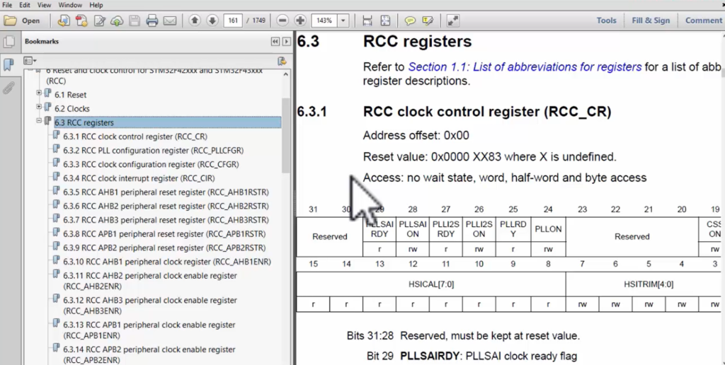
In the peripheral clock enable registers, AHB1 peripheral clock register is used to enable the clocks for those peripherals which are hanging on the AHB1 bus.
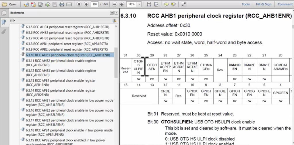
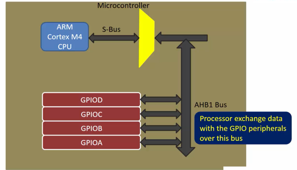
In our case, the GPIOD peripheral is actually hanging on the AHB1 bus. So, if you are thinking how come I know this information. This information you can get from the data sheet of the microcontroller.
Let’s open the data sheet of the microcontroller.

Figure 4 shows the internal architecture of this microcontroller. So, if you can spot the processor here. ARM Cortex-M4 168 MHz FPU is a processor and GPIO PORT D is a peripheral. And look how they communicate.
The GPIOD peripheral is connected to the AHB1 bus and then that is further connected to the processor via this AHB bus matrix. That’s why I can say that GPIOD is connected to the AHB1 bus.
Figure 3 is a simplified diagram actually. There is an AHB bus and the data exchange between peripheral and memory happens over the bus.
Let’s go back to our RCC Register discussion.
In the RCC registers, we should be looking at RCC AHB1 peripheral clock register. Because this register controls clocks for all the peripherals which are hanging on the AHB1 bus.

What is the address of this register?
Let’s calculate that. The documentation says that the offset is 0x30. That means you have to add this offset to the base address of the RCC peripheral registers.
What is the base address of the RCC peripheral registers?
0x40023800 is the base address of the RCC peripheral registers.
This information again you get from the memory map of the microcontroller. Open the memory map, and find RCC, there is a base address. So, you have to add that offset to that base address to get the address of this register.
And here you have to activate or set the 3rd-bit position, that is GPIOD EN. You can see that, Bit 3 is a position to turn on the clock for GPIOD peripherals.
Now let’s explore the 3rd-bit position.

GPIOD enable is shown in Figure 6. IO port D clock enable. This bit is set and cleared by the software.
So, if you make this bit as 0, the IO port D clock will be disabled. If you make this bit as 1, the IO port D clock will be enabled.
Similarly, if you set bit field 1, then GPIO port A clock will be enabled. It’s like that. And also you have to pay attention to the reset value of this register.
That’s about how you enable the clock for a particular peripheral.
So, first, you have to identify which register you have to use in the RCC block to control the clock, and then you have to program the appropriate bit fields.
FastBit Embedded Brain Academy Courses
Click here: https://fastbitlab.com/course1


