I2C Protocol Explanation
Introduction to I2C Protocol:
The I2C (Inter-Integrated Circuit) protocol is a widely used serial bus protocol for communication between electronic devices.
Signal Lines:
The I2C is a serial bus protocol consisting of two signal lines such as SCL and SDL lines which are used to communicate with the devices.
- SCL stands for a ‘serial clock line,’ and this signal is always driven by the ‘master device.’
- SDL stands for the ‘serial data line,’ and the SDL signal is generated by either the master or the I2C peripherals.
Both these SCL and SDL lines are in an open-drain state when there is no transfer between I2C peripherals.
How I2C works?
Message Structure:
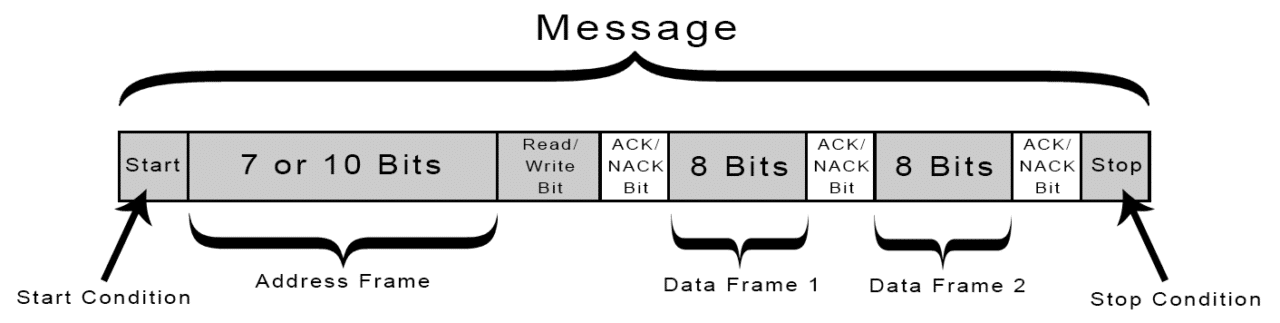
In I2C communication, data is transferred in the form of messages. Messages are broken up into frames of data.
Each message has an address frame that contains the binary address of the slave, and one or more data frames that contain the data being transmitted.
The message also includes start and stop conditions, read/write bits, and ACK/NACK bits between each data frame.
Address Phase:
From Figure 1. The master begins the transfer by first producing start condition. After the start condition, the address phase follows. The address phase is 8-bits. The address phase is a collection of the slave address and read-write bit.
In the address phase, the first 7-bits are the address of the slave. So, the slave address is 7-bits. The remaining one bit decides to read or write operation, and this is called R/nW.
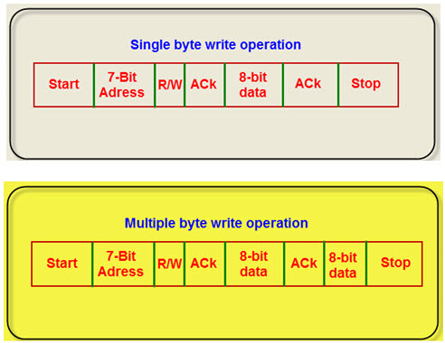
Write Operation
If R/nW bit is 0, that indicates master is going to write the data or master is going to transmit the data, this is called a write operation.
Read Operation
If R/nW bit is 1, that indicates master is going to read data from the slave, and this is called read operation. So, read means read from the slave and write means write to the slave.
Let’s assume that R/nW bit is 0, so collectively the address bit is of 8 bits. That means every byte put on the SDA line must be 8 bits long. Each byte followed by an acknowledge bit.
In the address phase, the master is going to send 7 bits, and the slave is going to receive these 7 bits. Then the slave is going to match its address with a 7-bit slave address sent. If there is any match, then the slave is going to ship an acknowledgment (ACK) to the master.
So, once the master receives the ACK, it is going to write operation. That means the master is going to do write or transmit one byte of data to the slave because R/nW is 0. When the slave receives this 1 byte of data, slave going to send ACK saying that it collected data byte.
Data Transfer Order
Remember that the data transferred with the most significant bit first. When the master wants to send more data to the slave and master can send more data. When the master decides to close the communication with the slave, the master generates a stop condition. So, in this way, the I2C protocol works. Figure 2. shows the I2C data transfer formats for a single write operation and multiple write operations.
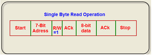
Now consider R/nW bit as 1, then master is going to read the data from the slave. The master initiates the transfer by first producing start condition.
In the address phase, the 8 bits are sent, the slave is going to receive these 8 bits. If there is any match, then the slave is going to send an acknowledgment (ACK) to the master. So, once the master receives the ACK, it is going to do read operation. That means the master receives the data from the slave, and now ACK is given by the master. If the master got sufficient data, then the master generates a stop condition. So the stop condition always releases the bus. The generation of stop condition causes the master has no control over the bus, and some other master can initiate the data transfer.
Remember that after the start condition master holds the line and after stop condition master releases the line. Figure 3. shows the I2C data read format for a single byte.
In the following article, we learn I2C START and STOP conditions.