USART interrupt discussion
In this article, let’s discuss USART interrupts.
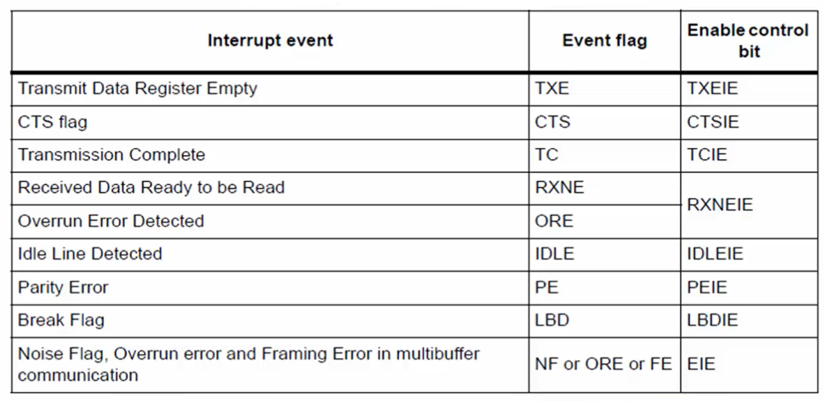
The interrupt events triggered by the USART peripheral are, as listed in Figure 1, and in the third column, you can see the respective control bits.
In the event flag column, you can see the flags corresponding to each event, which will get set when the corresponding event happens during the UART communication, and the setting of any of these flags have the capacity to generate interrupts only if the respective control bits are enabled.
Some important interrupt events triggered by the USART peripheral is listed as follows:
- Transmit Data Register Empty: This is actually a TXE interrupt.
- CTS flag: this is to do with hardware flow control. That means when a CTS flag is set, it can generate an interrupt if the CTSIE control bit is enabled.
- Transmission Control (TC)
- Received Data Ready to be Read: This is actually an RXNE interrupt.
- Overrun Error Detected: Whenever an overrun happens during the reception, then it can generate an interrupt if the RXNEIE control bit is enabled.
- Idle Line Detected: After transmitting all the frames, the line becomes idle, which is actually an idle line. Whenever an idle line is detected, it can also generate an interrupt if the IDLEIE bit is enabled in the control register.
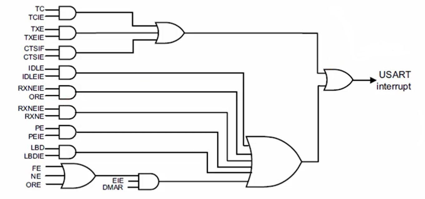
In Figure 2, you can see a USART interrupt mapping diagram. In which you can see that there is only one line that goes from each USART peripheral, and it will hit the NVIC engine of the processor.
In I2C, you saw two lines coming out from each USART peripheral. One for the error and another for the event. But here, it is not like that. You can analyze the USART interrupt mapping diagram from the reference manual.
Exercise:
- Complete the interrupt APIs. The implementation of interrupt APIs should be done similar to what you did for I2C and SPI.
- After that, give the USART IRQ definition macros in the MCU specific header file.
FastBit Embedded Brain Academy Courses
Click here: https://fastbitlab.com/course1

