Exercise-008:Implementation part 5
In this article, let’s code for main.c.
First, we will check the main.cpp. Here, we have to modify a couple of things.
#include <Arduino.h>
#include "qpn.h"
#include "ClockAlarm_SM.h"
#include "button_SM.h"
#include "lcd.h"
#include "main.h"

Q_DEFINE_THIS_FILE;

bool flag_report_button_press = true;

static void sys_tick_init(void);
static void display_init(void);
static void attach_button_interrupts(void);

static QEvt ClockAlarmQueue[8];
static QEvt ButtonQueue[8];

QActiveCB const QF_active[] = {
{ (QActive*) 0, (QEvt*) 0, 0},
{ (QActive*) AO_ClockAlarm,(QEvt*)ClockAlarmQueue,Q_DIM(ClockAlarmQueue)},
{ (QActive*) AO_Button,(QEvt*)ButtonQueue,Q_DIM(ButtonQueue)}
};

void setup() {
// put your setup code here, to run once:
Serial.begin(9600);
display_init();
attach_button_interrupts();
Clock_Alarm_ctor();
Button_ctor();
QF_init(Q_DIM(QF_active));
}

void loop() {
QF_run();
}

void SET_handler(){

QF_INT_DISABLE();
if(flag_report_button_press){
flag_report_button_press = false;
QActive_armX(AO_Button,0,MS_TO_TICKS(50),0U);
}
QF_INT_ENABLE();

}

void OK_handler(){
QF_INT_DISABLE();
if(flag_report_button_press){
flag_report_button_press = false;
QActive_armX(AO_Button,0,MS_TO_TICKS(50),0U);
}
QF_INT_ENABLE();
}


static void attach_button_interrupts(void)
{
attachInterrupt(digitalPinToInterrupt(PIN_BUTTON1), SET_handler, RISING);
attachInterrupt(digitalPinToInterrupt(PIN_BUTTON2), OK_handler, RISING);
}

static void sys_tick_init(void){
TCCR1A = TCCR1A_CTC_MODE; //CTC mode
TCCR1B = (TCCR1B_CTC_MODE |TCCR1B_PRESCALER_1); //prescaler=1,CTC mode
TIMSK1 |= B00000010; //Interrupt enable for OCR1A compare match
OCR1A = TIMER1_OC_MATCH_VALUE; //OC match value for CONFIG_TICKS_PER_SECOND time base generation
}


static void display_init(void)
{
lcd_begin(16,2);
lcd_clear();
lcd_move_cursor_L_to_R();
lcd_set_cursor(0,0);
lcd_no_auto_scroll();
lcd_cursor_off();
}

void QF_onStartup(void)
{
sys_tick_init();
}

void QV_onIdle(void){
QV_CPU_SLEEP();
}

Q_NORETURN Q_onAssert ( char_t const Q_ROM *const module,int_t const location ){
Serial.println("Assertion failure!!");
Serial.println((String)module);
Serial.println(location);
while(1);
}
main.cpp code
First of all, this button_pad_value function is not required now because we have a separate state machine for the button, and we’re also going to use button interrupts. That’s why the process_button_pad_value function is not required now. I am removing this whole function.
Q_onAssert function is required, display_init it is required, and a Timer1_setup is required, but we have to modify that. We will do that later.
In the loop function, we are going to delete everything. All these codes are not required because we are not sending the events like this. All events are delivered to the Event queues of the Active object asynchronously. Such a polling code is not required. I’m going to remove everything which is there in the loop function. Now the loop function is empty.
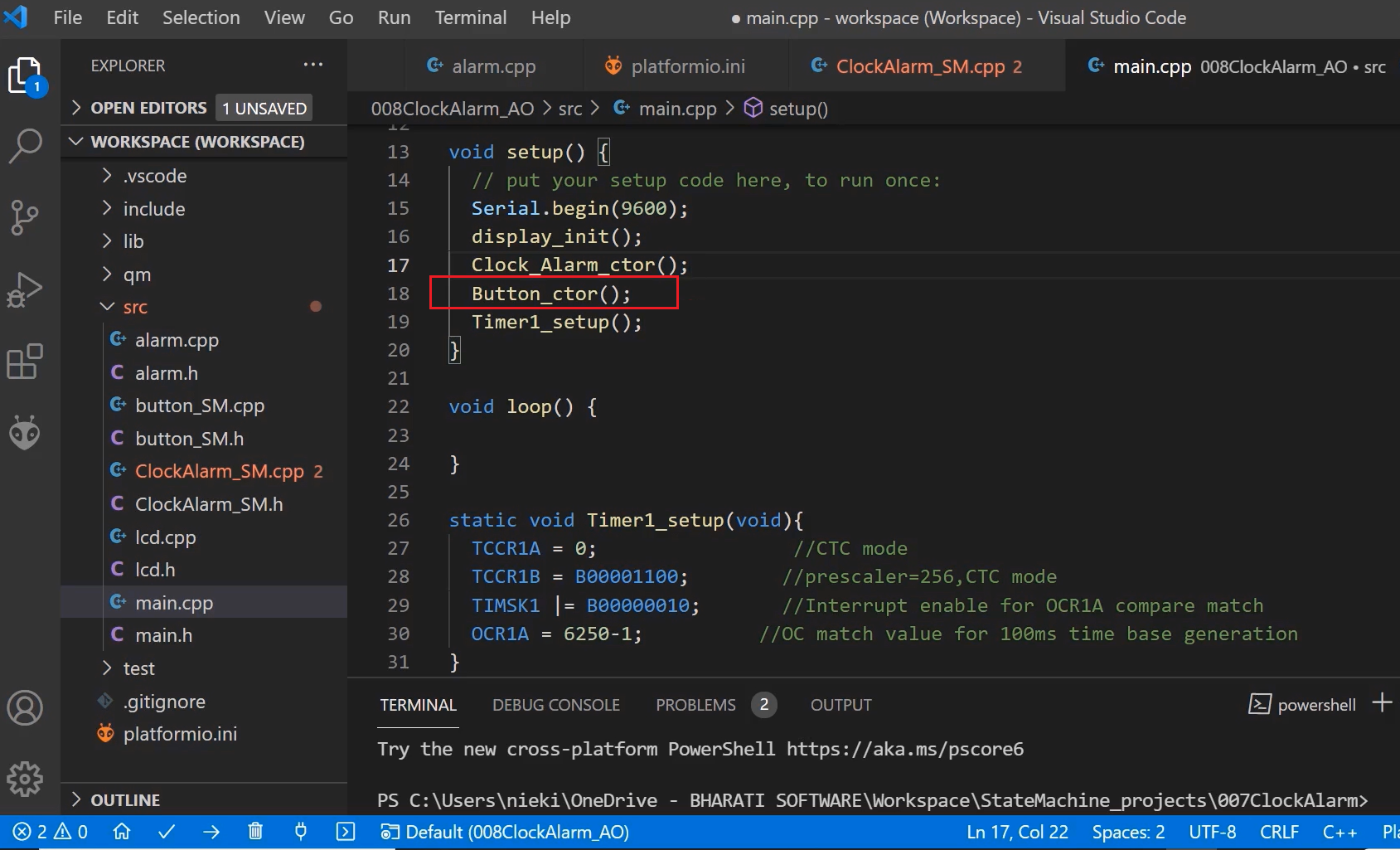
In the setup function, Serial.begin(9600) is required; a display_init is required. This QHSM_INIT is not required, so we will remove that. And after the display_init, we are calling the ctor of our Clock_Alarm class. But, we have two main classes in our project. Another one is the button class. That’s why we have to call the ctor of that as well.
For that, let’s add the header file at the top, #include “button_SM.h”. This file exposes Button_ctor function.
In the main.cpp, and after ClockAlarm_ctor, we will call this Button_ctor function, shown in above code.
And what we do in the Clock_Alarm_ctor, as you can see below, Clock_Alarm_ctor is a implementation, and it has one component.
void Clock_Alarm_ctor(void) {
          Alarm_ctor(&Clock_Alarm_obj.alarm);
         QActive_ctor(AO_ClockAlarm,Q_STATE_CAST(&Clock_Alarm_initial));
}
Clock_Alarm_ctor function
Now, this ctor should call the ctor of its components. That’s why, let’s call here the ctor of the component, that is alarm_ctor. And how is that exposed? That is exposed through the alarm.h.
Clock_Alarm_ctor is a container, and we will call the ctor of the component ‘Alarm_ctor().’
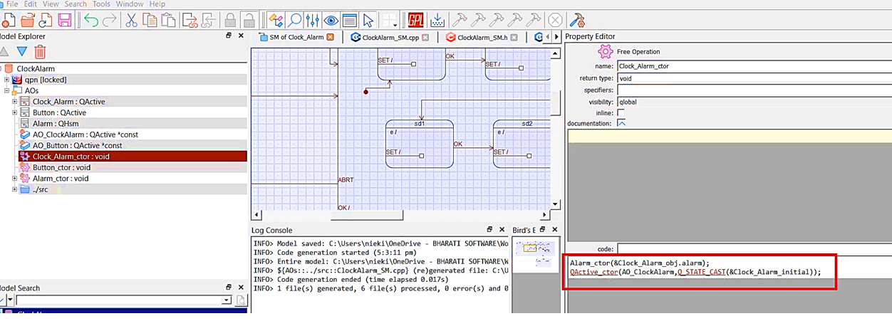
And for this, the Alarm_ctor function needs a pointer to the alarm class. That we can easily get from the object ‘&Clock_Alarm_obj.alarm’. And this we shouldn’t be doing in this IDE because I cannot edit this here. That’s why I’m going to copy this code to the model.
In the model, I’m pasting that code in Clock_Alarm_ctor. And save it, generate the code.
After that, when the Clock_Alarm_ctor gets called, it calls Alarm_ctor. And inside the Alarm_ctor, we initialize the state variable to Alarm_initial, which is the address of the initial state handler of the alarm state machine. (Figure 2)
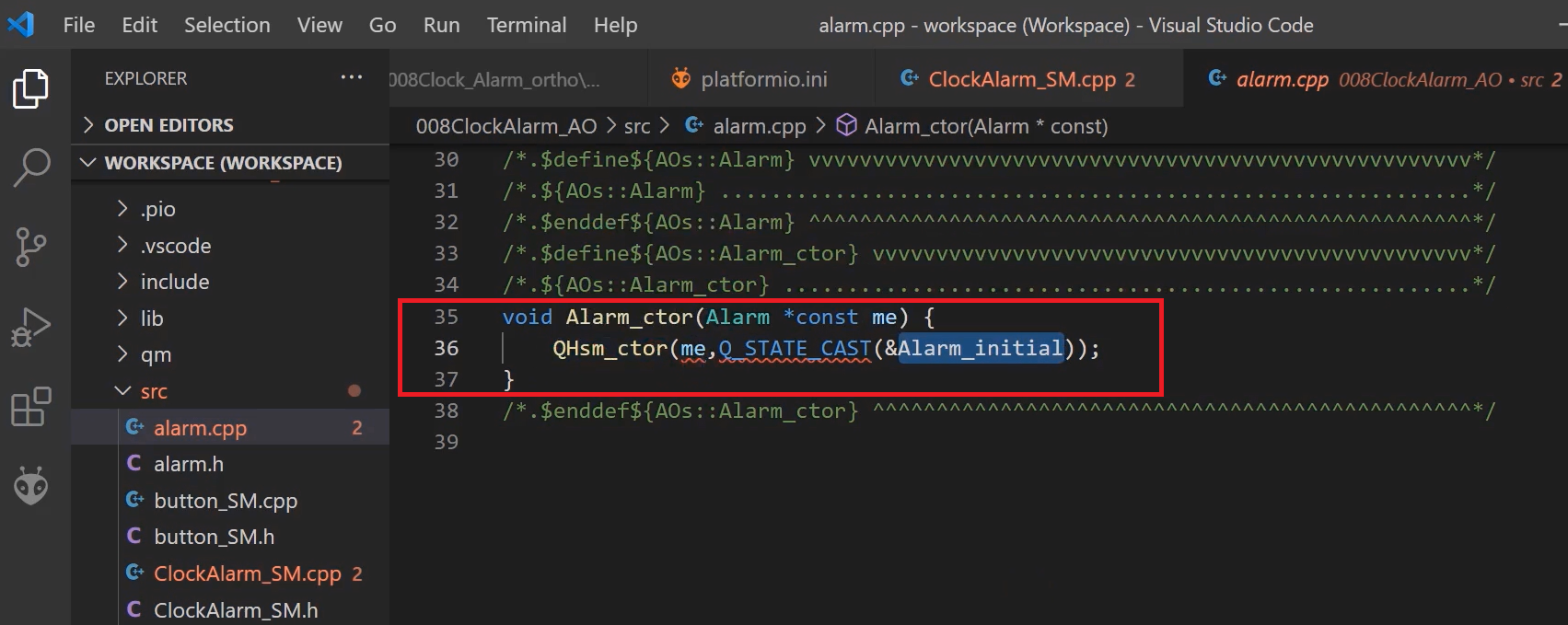
When you call the ctor of the Clock_Alarm class, that actually calls the ctor of all of its components. That’s how the Alarm_ctor gets called. And in the Alarm_ctor, we do QHsm_ctor. That is we call the ctor of the superclass. And the superclass of the Alarm class is QHsm. And you also know that this QHsm_ctor call initializes this Alarm_initial pointer or handler address to the state variable of the QHsm superclass.
After QHsm_ctor, you have to call QHsm_init, which executes the Alarm_initial function. That’s how the initial transition actions are executed.
Now, where to do QHsm_init? That you can do here.
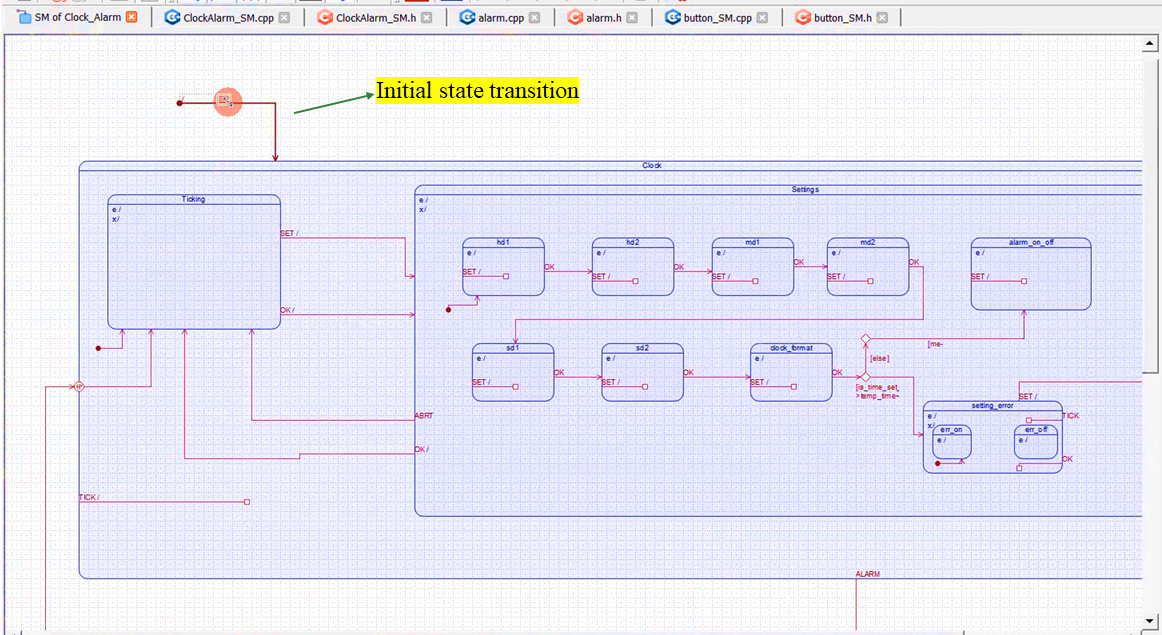
Let’s go to the model. See Figure 3, this is our main state machine, the state machine of the Clock_Alarm, and there is an initial state transition.
And from here, we will call the init function of the component. The component is the Alarm. We will create one function or an Alarm class operation. Right-click on Alarm and select Add Operation. I will name it as init, and the return type is void, visibility is public, and the code is you have to call QHSM_INIT from here.
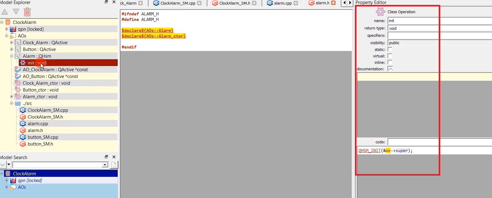
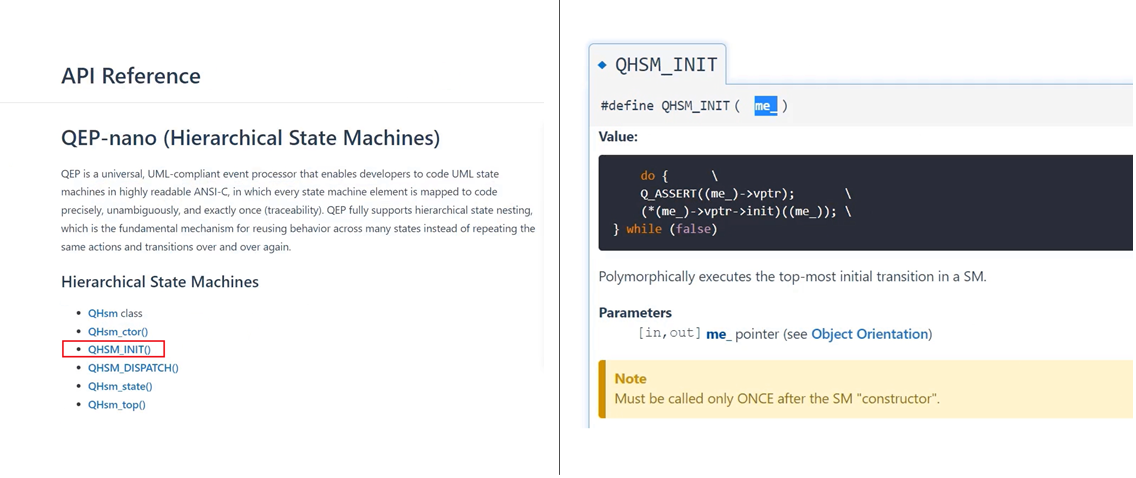
For the QHSM_INIT, what are the arguments? You see, after QHsm_ctor, you have to call QHSM_INIT.
You have to mention the address of the superclass for this(me).
Let’s go back to the model. And here in the code you write QHSM_Init, it is &me-> super. QHSM_Init code shown in Figure 4 you see.
After that, we will call this init function from the clock alarms initial transition from here, as shown in Figure 6.
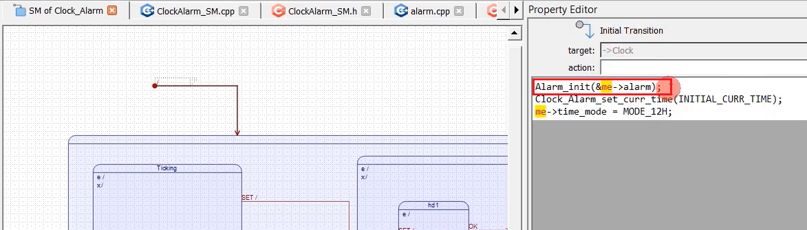
Alarm_init(&me->alarm); You can get the ‘me’ pointer. Because the initial transition has access to the ‘me’ pointer. You can generate the code.
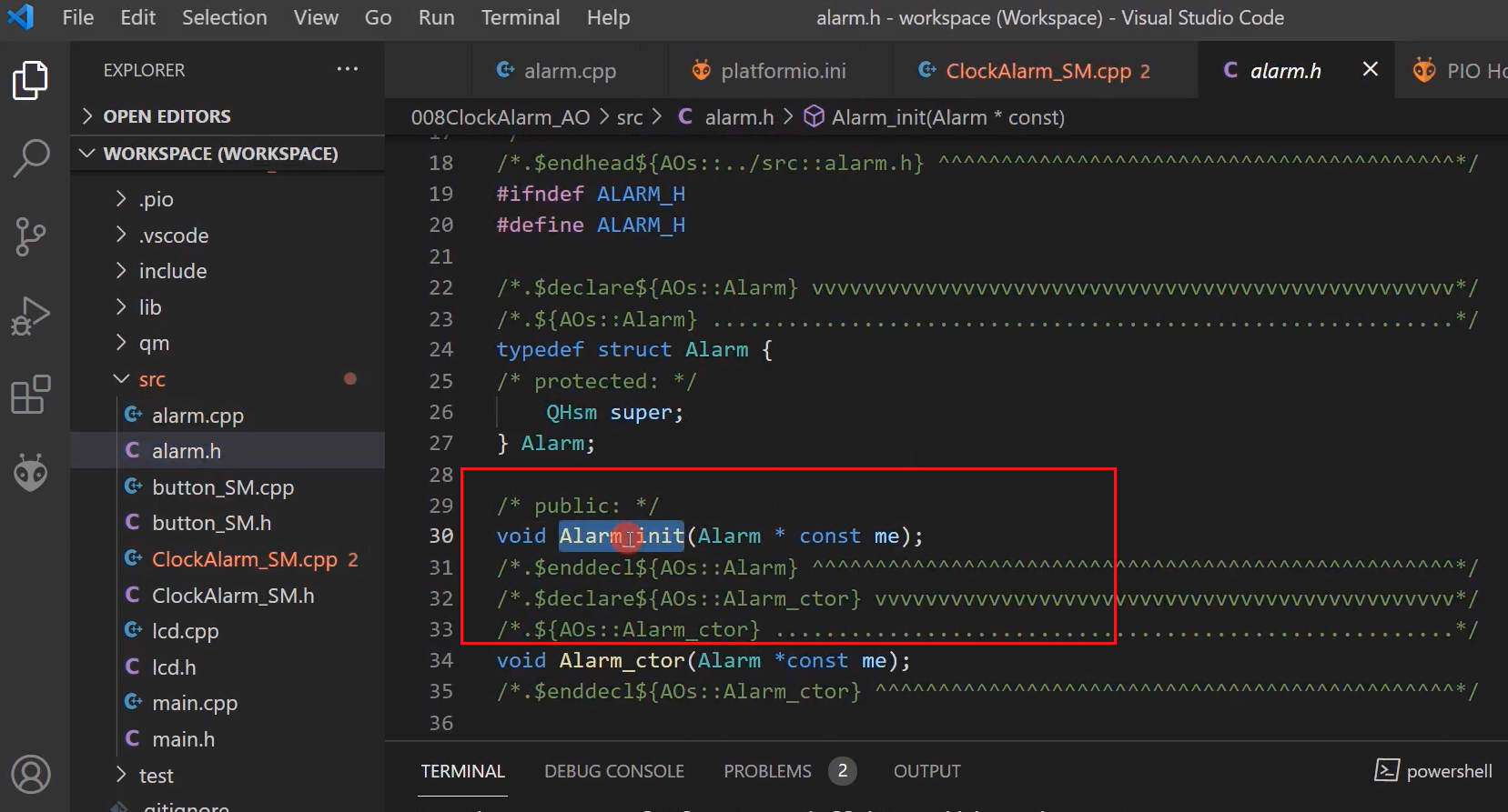
Now you can see that in the alarm.h, there is a function Alarm_init, which will be called by this file ClockAlarm_SM.cpp.
Now, let’s go back to the main.cpp, and in the setup function, we have to call Button_ctor. After that, we have to implement the button interrupt handlers. Because we have to catch the button press via the interrupts. In the Arduino framework, you can easily implement the button interrupts. I mean, or the external interrupts. It’s very easy.
Let’s go to the Arduino home page and go to the reference.

Here functions (as shown in Figure 10). Go to interrupts or you can go to external interrupts.
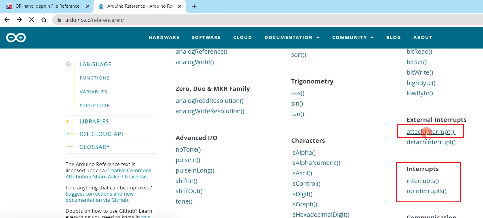
attachInterrupt() → By using this function, you can attach an interrupt. How to use this? It’s already mentioned here.
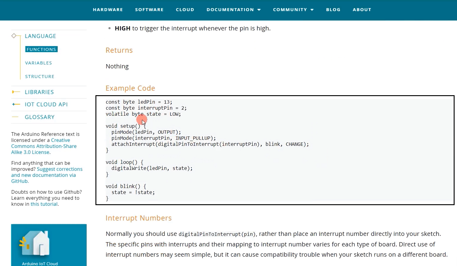
For example, if you want to receive an interrupt on pin 2, then you have to use this attachInterrupt function. attachInterrupt(digitalPinToInterrupt(interruptPin), blink, CHANGE)
Mention the pin number, and mention the handler name. Here, the handler name is ‘blink .’ When that interrupt happens, the blink function will get called.
And when should interrupts trigger? Whether it should trigger during the rising edge of the signal, a falling edge, or there are other options. Here it is (Figure 12).
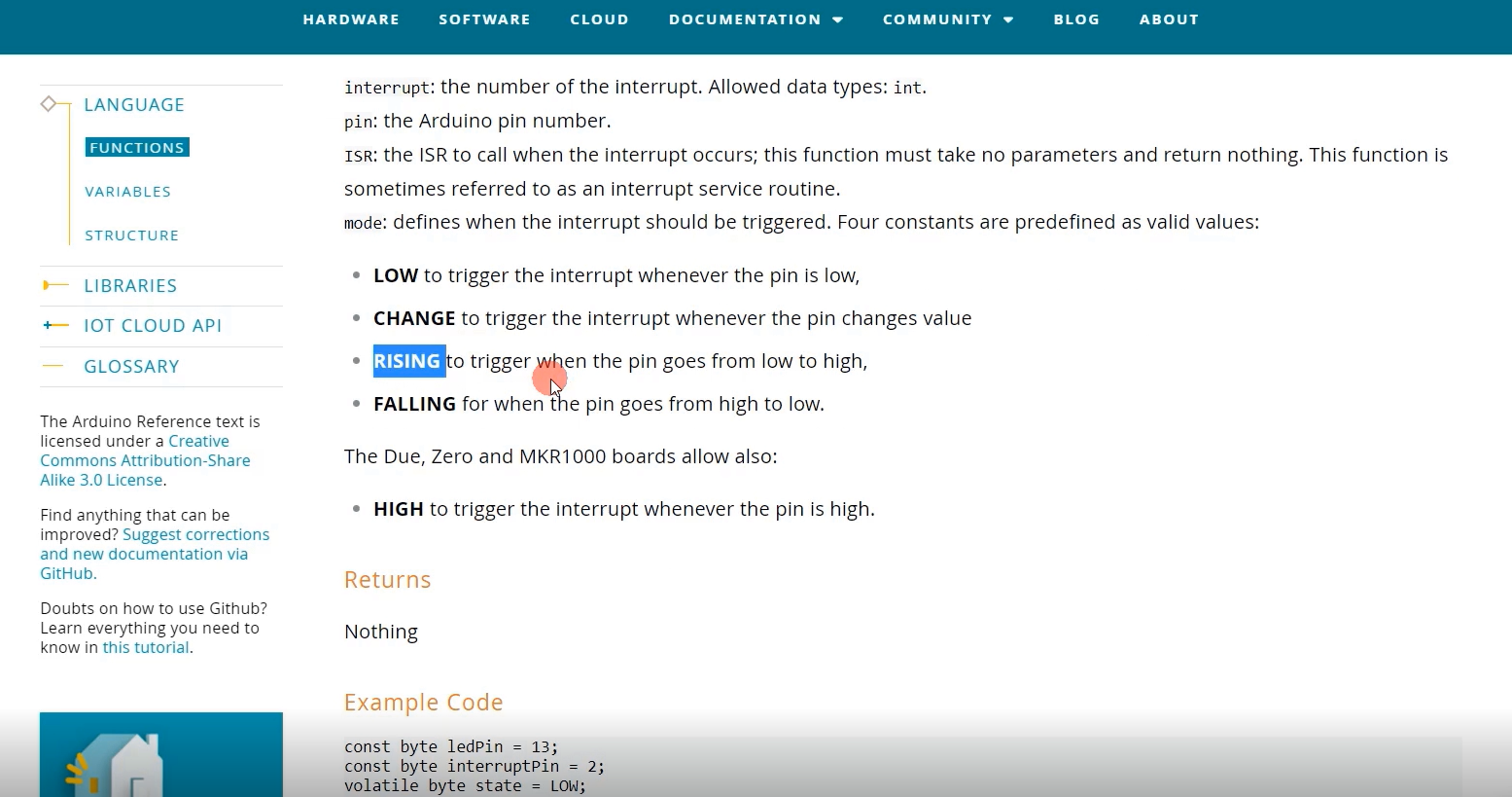
Trigger the interrupt whenever the pin is low, whenever the pin status changes, like that. We will go for RISING. Because, in our circuit, whenever the user presses a button, there will be a low to high transition. That’s why we will use RISING.
I’ll take the attachInterrupt(digitalPinToInterrupt(interruptPin), blink, CHANGE) function and let’s go to our code.
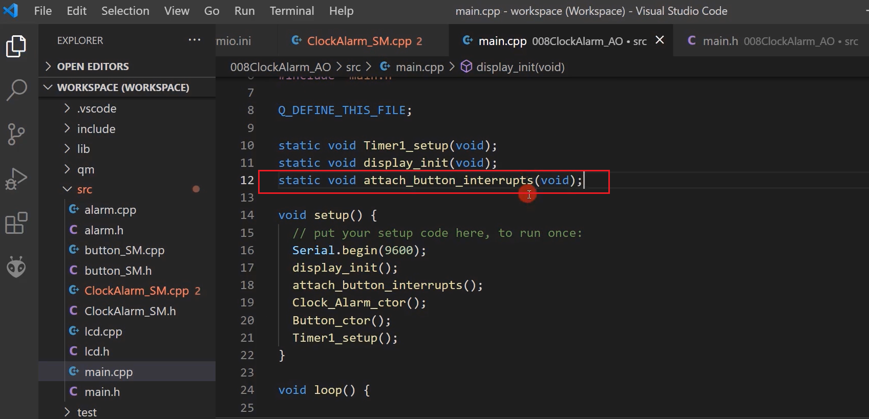
In setup, I will write one function attach_button_interrupts() after the display init(). Let’s implement the attach_button_interrupts() function here.
And we have to call this attachInterrupt(digitalPinToInterrupt(interruptPin), blink, CHANGE) function twice. And Change will be RISING. We will change blink as the OK handler and SET handler. And we will implement that function after the loop function. void SET_handler and another function will be the void OK_handler.
Here you have to mention PIN_BUTTON1 and PIN_BUTTON2.
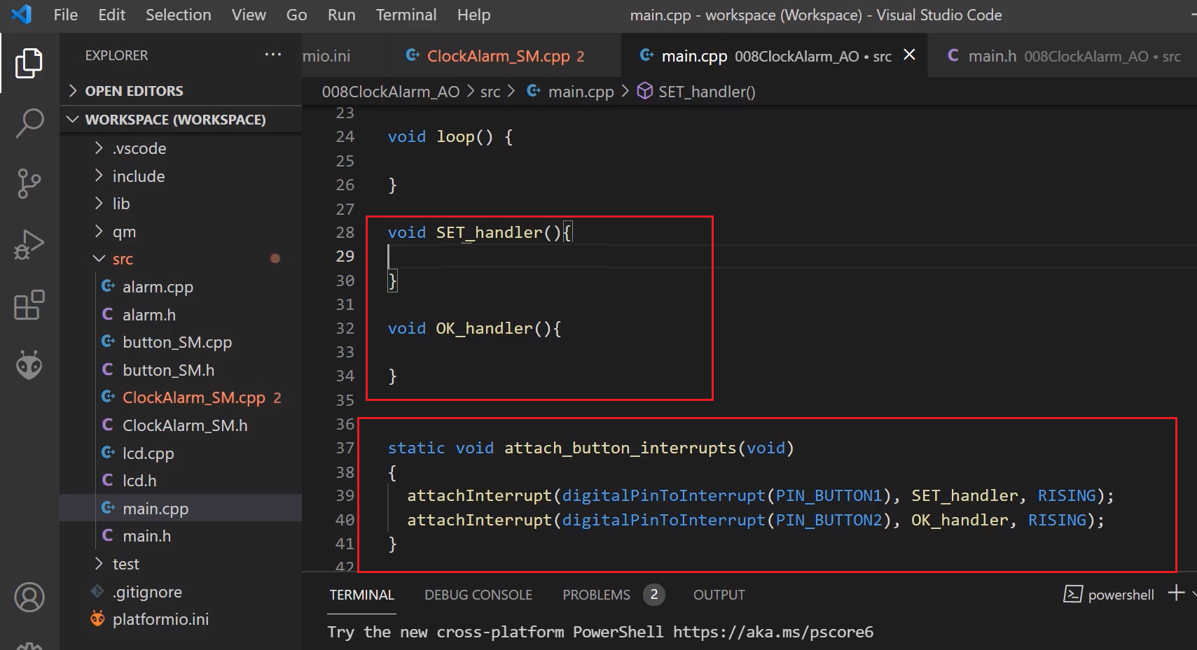
PIN_BUTTON1 and PIN_BUTTON2, these macros are there in main.h. PIN_BUTTON1 is our ‘SET’ button, and PIN_BUTTON2 is the ‘OK’ button.
#define PIN_BUTTON1 2 //SET
#define PIN_BUTTON2 3 //OK
#define PIN_BUZZER 12
main.h, PIN_BUTTON macros
Let’s give the prototype here, as shown in figure 14.
When the ‘SET’ button is pressed, SET_handler will get called, so we have to post an event. We have to post an event to the event queue of the button active object.
FastBit Embedded Brain Academy Courses
Click here: https://fastbitlab.com/course1