Exercise-008:Implementation part 6
In this article, to use the QP-Nanos Active Object Framework, you have to implement a couple of steps. Let’s discuss that now.
- First, you have to create the event queues for the active objects that you have used in your application. In our application, we have used two active objects. We have to create two event queues. It is nothing but just a static array of QEvt structure.
- After that, you have to create and initialize the Active object control block. It is nothing but there is a structure called QActiveCB. So, you have to create an array instance of this structure, and you have to initialize that.
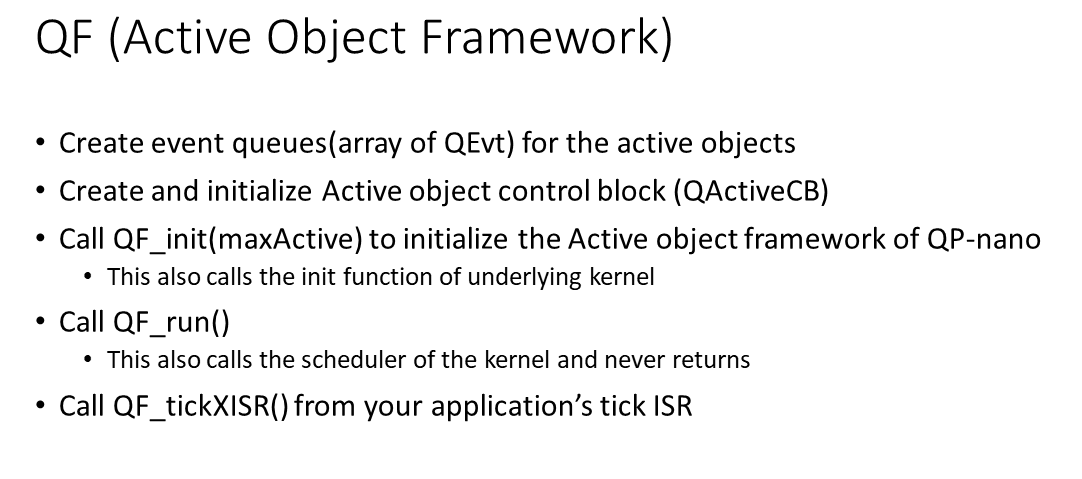
- After that, you have to call QF_init, and you have to mention the number of active objects used by your application. And this is to initialize the Active object framework of QP-nano. It accesses all the Active objects what you have mentioned in the control block, and it initializes that.
This also calls the init function of the underlying kernel. So, the underlying kernel in our case is QV, which is the cooperative vanilla kernel.
- After that, you have to call QF_run. This also calls the scheduler of the kernel, and it never returns.
- And after that, if you want the framework to generate timeout events, a timeout could be a one-shot or periodic timeout. You have to use this function QF_tickXISR. This function should be called from your application’s tick ISR. That means your application now should provide one a periodic tick ISR, which is already there in our application. So, we have already used timer1 peripheral to generate a periodic interrupt for every 100 milliseconds. We will slightly modify that.
And we’ll use that as our tick ISR because every RTOS or kernel should use a background tick ISR. And from that background tick ISR, you have to call this function. So, this gives the framework a chance to update all its time-related events.
Let’s implement all these steps. Let’s first start with step 1, Create event queues.
Now, let’s get back to the code main.cpp. We will create two arrays of QEvt type. We will create two arrays.
So, the first array is ClockAlarmQueue and ButtonQueues of type a QEvt, and we will give space for 5 events. These are statically defined Event queues for our Active objects.
static QEvt ClockAlarmQueue[5];
static QEvt ButtonQueue[5];
The next step is to create and initialize an Active object control block. Now, let’s create a variable of QActiveCB. So, if you want to read about QActiveCB structures, check here in ‘qfn.h’, as shown in Figure 2.
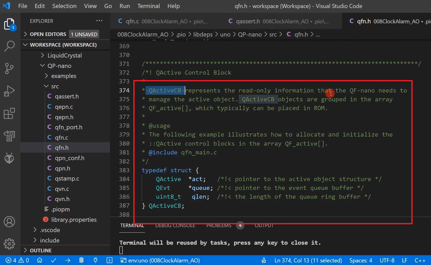
QActiveCB represents the read-only information that the QF-nano needs to manage the active object. The QActiveCB objects are grouped in the array QF_active[].
Basically, it has three fields. Pointer to your active object, a pointer to the event queue of the active object, and here you must mention the length of the Event queue of your active object.
So, you have to create a QF_active array now. Let’s do that.
QActiveCB const QF_active[] = {
  { (QActive*) 0, (QEvt*) 0, 0},
  { (QActive*) AO_ClockAlarm,(QEvt*)ClockAlarmQueue,Q_DIM(ClockAlarmQueue)},
  { (QActive*) AO_Button,(QEvt*)ButtonQueue,Q_DIM(ButtonQueue)}
};
QActiveCB
QActiveCB const QF_active[] and let’s initialize this with all the active objects. The first entry should be a Null entry, and you can do like this Qactive*. You can just typecast to QActive*. And the second member element is a pointer to the event queue; you can write like this QEvt*. And the third one is the length, which is 0.
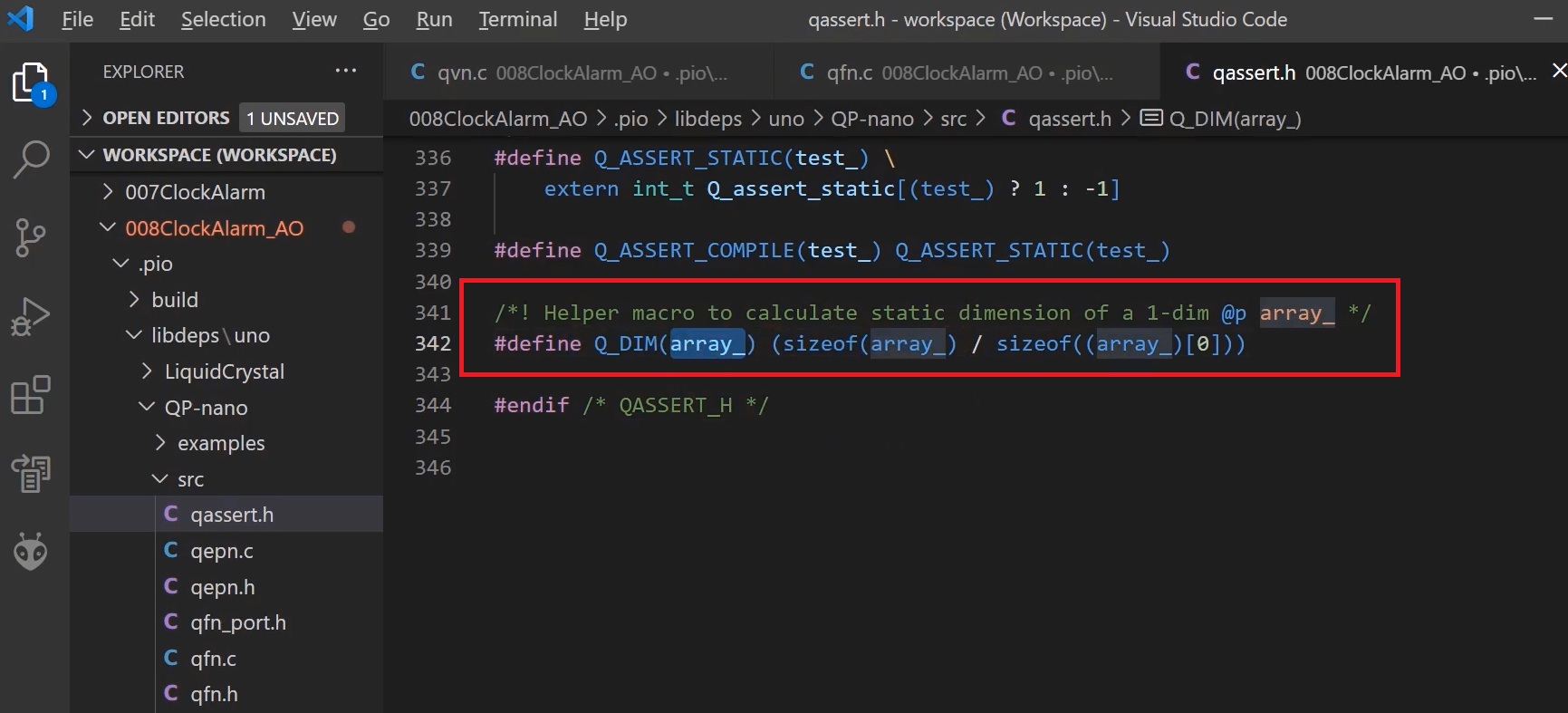
After that, the second entry you start with your first active object, that is AO_ClockAlarm; address of the Event queue, that is ClockAlarmQueue; And length. The length of this is ClockAlarmQueue. For this, you can use this macro Q_DIM; you mention the array name like this. You can do like for AO_Button.
Q_DIM macro helps you to calculate the number of elements in the given array(Figure 4). QActiveCB code is shown above. We created the Active object control block.
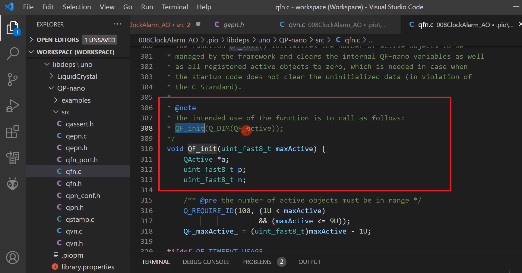
The third step is QF_init. This QF_init is there in qvn.c. The proper usage of this function is mentioned here (Figure 5).
You have to send a number of active objects your application uses, which can be calculated using Q_DIM macro over QF_active array variable. Let’s do that.
After the button_ctor, we can do that. QF_init, let’s use the Q_DIM of this QF_active, as shown below.
void setup() {
  // put your setup code here, to run once:
  Serial.begin(9600);
  display_init();
  attach_button_interrupts();
  Clock_Alarm_ctor();
  Button_ctor();
  QF_init(Q_DIM(QF_active));

  Timer1_setup();
}
QF_init code
And after that fourth step is QF_run. QF_run can be called from the loop function because you cannot call QF_run in the setup function. Because it never returns.
QF_run, as you can see here, is there in qvn.c. This has one giant loop here, which is a scheduler, you see that in Figure 6. It executes the events for the active objects in a cooperative manner.
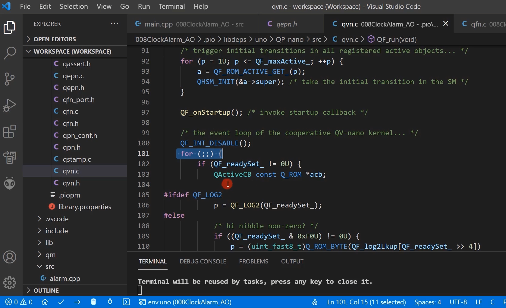
If there are no events to be processed, then it calls the Idle hook function. This Idle hook function must be implemented in your application.
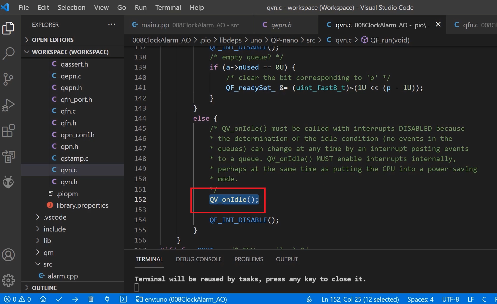
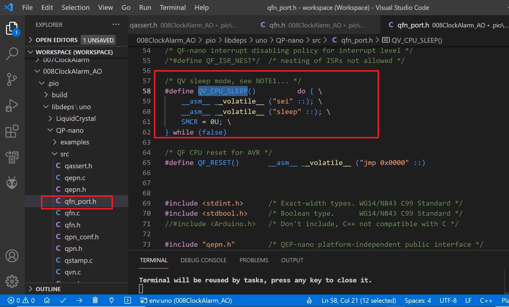
We will implement the QV_onIdle function in our main.c. So, you can here put the processor to sleep, that sleep-related function also given in the qfn_port.h. This is a port for the avr based microcontroller. You can see that(Figure 8), there is already a macro present QV_CPU_SLEEP. So, it enables the interrupt, and it just sleeps. We will call this function from there. Let’s go to the main.cpp, and we’ll call that function, as shown below.
void QV_onIdle(void){
   QV_CPU_SLEEP();
}
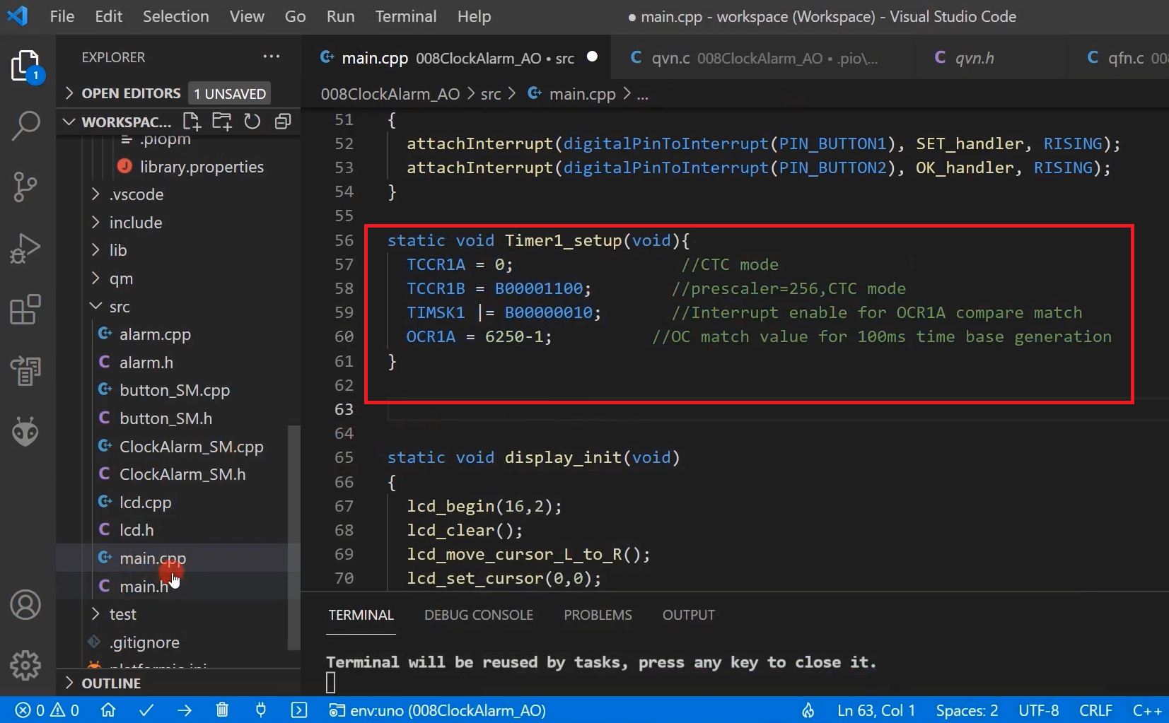
After that, the next step is to call the OF_tickXISR function from your application’s tick ISR. And we already have this Timer1_setup. What does it? It generates an interrupt for every 100 milliseconds. What we will do is we will modify this Timer1 interrupt code to generate an interrupt for every 1 millisecond. That will be our tick ISR.
And from that tick ISR, we will call that function. That’s why we have to slightly modify this now to generate the timer interrupt for every 1 millisecond.
So, for that, I’ll be using some macros. I’ll put that in main.h.
Let’s go to the main.h, and I’m going to use some macros. So, these macros are very simple, as shown in Figure 10.
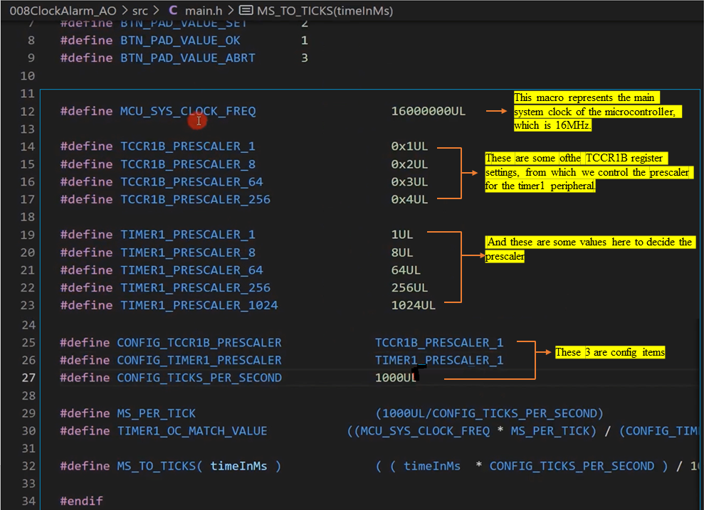
We can modify the config items. Currently, I have set the TCCR1B_PRESCALER to TCCR1B_PRESCALER1, which means no clock division. And CONFIG_TIMER1_PRESCALER to this value TIMER1_PRESCALER_1. So basically, this is nothing but 1.
CONFIG_TICKS_PER_SECOND represents the rate of the tick interrupts. TICKS_PER_SECOND means 1000 ticks per second. That means 100Hz. For every 1 second, there will be 1000 timer interrupts. That means 1 timer interrupt will arrive for every 1 millisecond. So, that’s a rate.
And MS_PER_TICK is a macro, which calculates milliseconds per tick. You have to divide 1000 milliseconds by CONFIG_TICKS_PER_SECOND.
And then TIMER1_OC_MATCH_VALUE calculates the Timer1’s match value, the match value that you need to configure into the timer once output compare register to get the tick rate of this much (CONFIG_TICKS_PER_SECOND).
MS_TO_TICKS is a helper macro, which converts milliseconds to ticks.
We will slightly modify our Timer1_setup code. Now I will change Timer1_setup to sys_tick_init. In the code, where is the timer1_setup, you change that to sys_tick_init. The modified code as shown below.
static void sys_tick_init(void){
   TCCR1A = TCCR1A_CTC_MODE;    //CTC mode
   TCCR1B = (TCCR1B_CTC_MODE |TCCR1B_PRESCALER_1);    //prescaler=1,CTC mode
   TIMSK1 |= B00000010;    //Interrupt enable for OCR1A compare match
   OCR1A = TIMER1_OC_MATCH_VALUE;    //OC match value for CONFIG_TICKS_PER_SECOND time base generation
}
After that, you have to call this function QF_tickXISR() from the tick ISR.
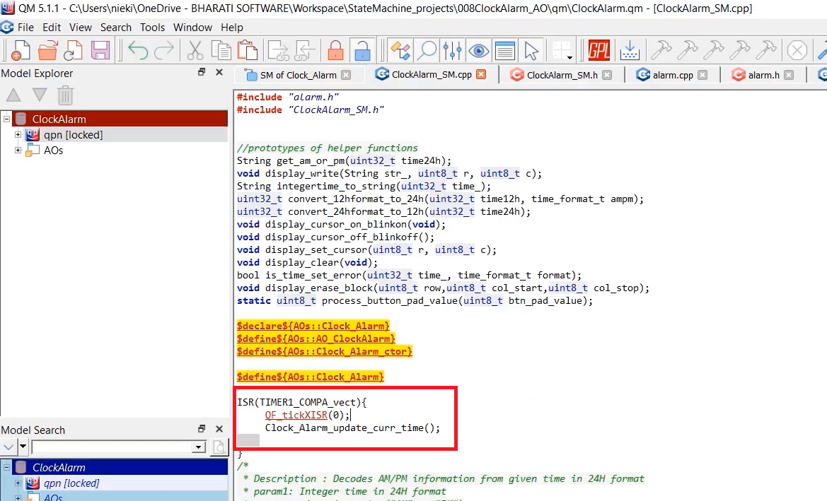
Let’s go to the model file. In the ClockAlarm_SM.cpp, we have the ISR. From here you should call. And you should send one argument to that function.
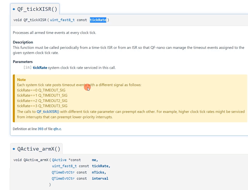
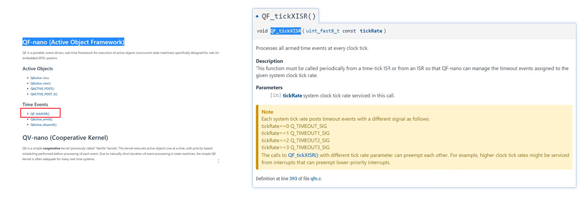
Why do you need to call QF_tickXISR?
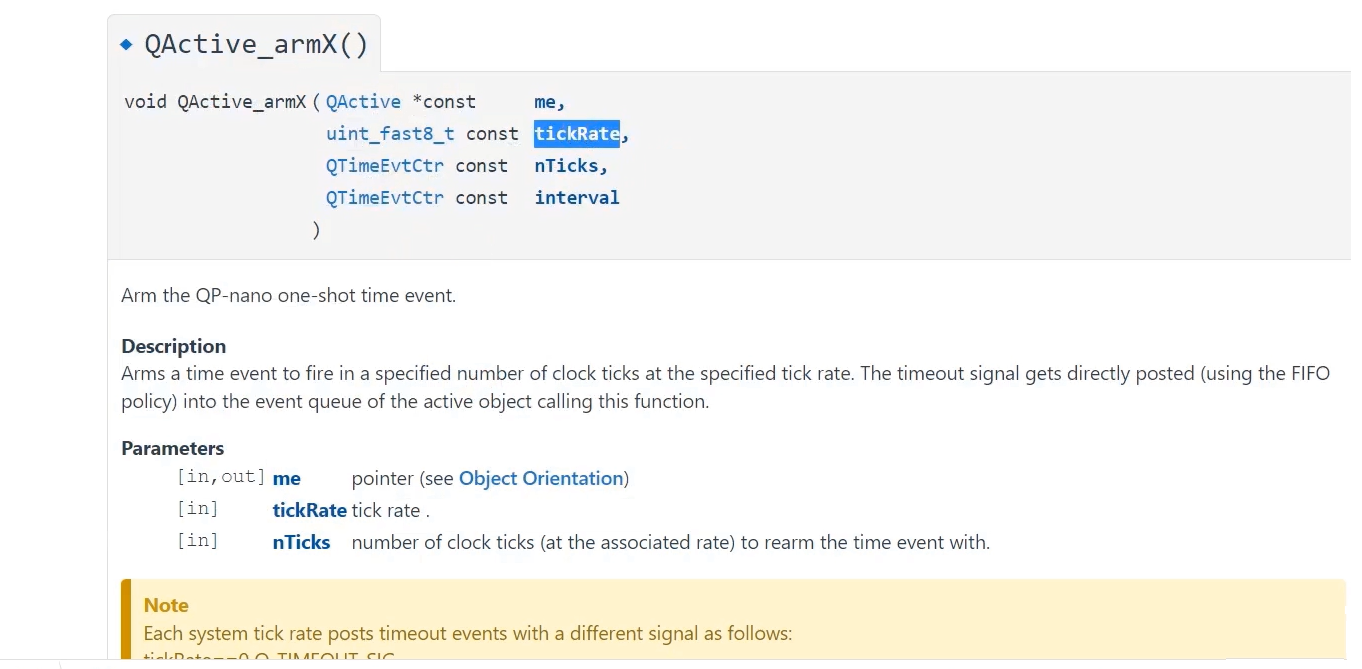
This gives the framework a chance to process all armed time events. The time events can be armed by using a QActive_armX and disarm function. You can arm for any timeout using the QActive_arm function.
As this description says, this function must be called periodically from the time-tick ISR. And you have to mention one argument, which is system clock tick rate, and this value can be 0 to 3. Basically, this identifies the system tick rate. Each system tick rate post timeout events with different signals are as follows. If we have used tick rate 0 here, when you use this QActive_arm function, then with that function, you have to mention the associated tick rate value. If it is 0 for example, the framework sends a timeout event with this name after a timeout Q_TIMEOUT. If the tick rate value is 1, the framework sends you a timeout signal with a signal name Q_TIMEOUT1 like that.
So, we will use 0 here in the model file, as shown in figure 12. QFtickISR(0).
Whenever you arm for a timeout using this QActive_arm function, for every invocation of the QFtickISR function, the framework checks whether there is really a timeout or not.
If there is a timeout, then it sends an event with the signal name Q_TIMEOUT if tickRate is 0; otherwise, Q_TIMEOUT1 if the tickRate is 1, like that.
Whenever a button press is detected, either ISR1 runs or ISR2 runs. We have got 2 button ISRs. Inside the ISR, we will use a flag. If this flag is true, then Arm_timer for the BOUNCE_TIME. Basically, it’s a one-shot timer. So, we will arm and one-shot timer for the BOUNCE_TIME. And when that BOUNCE_TIME is over, a framework sends a timeout signal to the Event Queue of the button active object. When the button active object receives the Q_TIMEOUT signal, it comes to know that someone has pressed the button and the bounce time is over. It can safely read the button status or the button pad status.
It reads the button status, it decodes that. So, it comes to know whether it needs to send a SET signal, OK signal, or ABRT signal, and that signal will be sent to the event queue of the Clock_Alarm AO.
Then, the button active object makes that flag = true. It will be a global flag shared between this button active object and the ISRs. So, you have to manage it in a thread-safe manner.
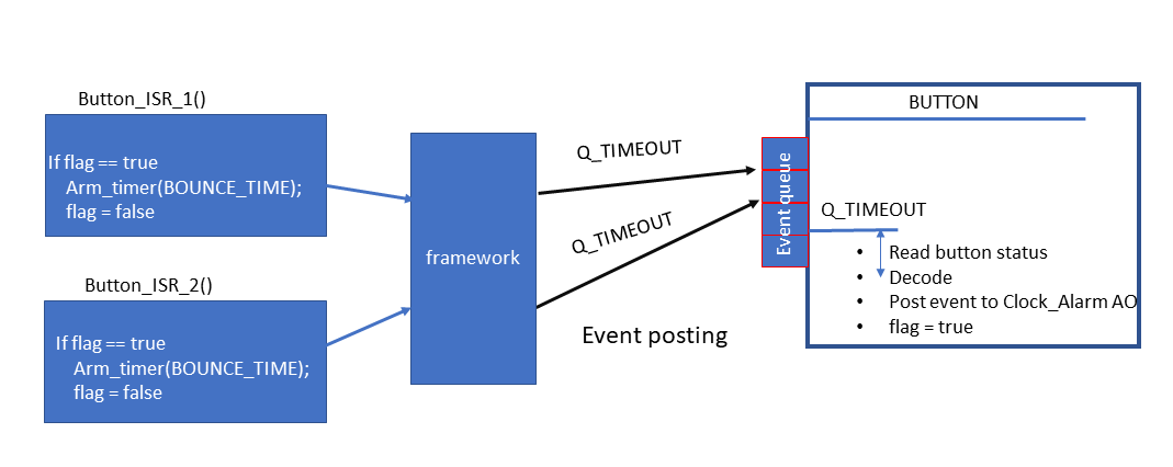
Now, we will implement this logic. If the button is bouncing here in Button_ISR_1, then this flag is since it is already false; that’s why this function will not get called for the next time until the button active object makes it ‘true’ again here. Now, we will implement this one.
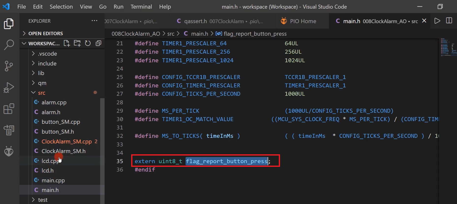
Let’s go back to the code. In the main.h, we will extern one variable. extern uint8_t flag_report_button_press, as shown in Figure 15.
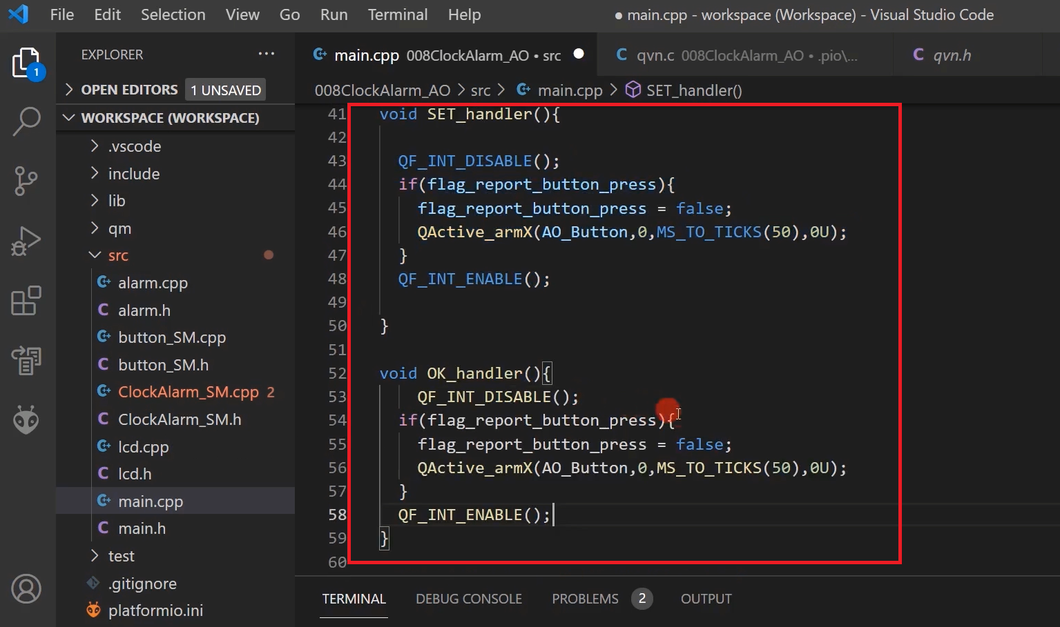
Now, let’s go to the ISRs. In the main.cpp, we have the ISR. Let’s go to the SET ISR. Here, let’s first disable the interrupt. You can use ‘cli’ instruction or use the macro provided by this framework, that is, QF_INT_DISABLE().
And after that, if that flag is true, then we will make it false, and we will use the QActive_armX function. What is ‘me’ here? See Figure 17; The timeout signal gets directly posted into the event queue of the active object pointed by this me pointer. That’s why this timeout event should be sent to the button active object. I will use AO_Button, the next event tickRate that is 0. And a number of ticks, we actually want a one-shot timeout for the bounce time. Bounce time is around 50 milliseconds. Let’s use the macro MS_TO_TICKS(50), which converts a number of milliseconds into ticks. After that, interval. Interval is not there because it’s a one-shot timer, so mention it as 0. After that, you can Enable the interrupt.
The same code you should place in OK_handler. The code is shown in Figure 16.
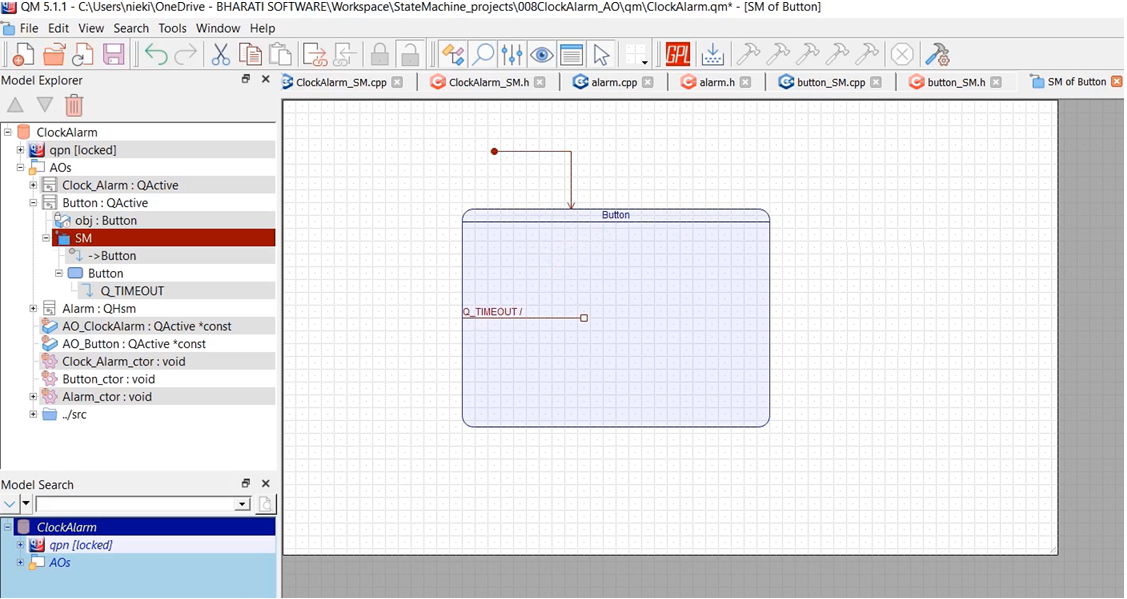
After that, let’s go to the model and draw the state machine for the button active object. The state machine is very simple in this case. It just have to process, so there will be one state. I’ll call this state a Button.
And in the state machine of the button also gives the initial transition, and there is nothing to initialize actually, because it doesn’t have any attributes.
It has only one transition, internal transition, whose name is Q_TIMEOUT.
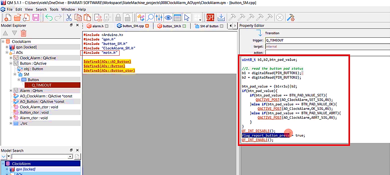
Whenever it receives a timeout, it should read the button status. The read the button pad status code shown in Figure 19.
So you have to post an event to the ClockAlarm active object. How to post an event? Let’s check.
Let’s go back to the APIs, Reference, and here it is QACTIVE_POST(). This is how you post. You have to call this macro QACTIVE_POST.
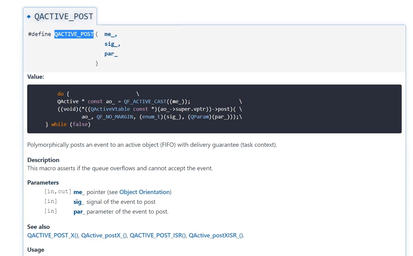
The ‘me’ pointer, the destination is an active object; AO → ClockAlarm, the signal is SET_SIG, and parameter. So, there is no parameter. Let me type 0. Let’s write this code for the OK signal and ABRT signal. And after that, make this flag = true again. And in the button_SM.cpp, you also include the “main.h” header file because it needs to access these macros and this variable.
In the following lecture, we will draw the state machine for the Alarm.
FastBit Embedded Brain Academy Courses
Click here: https://fastbitlab.com/course1