MCU pin configuration table and UART VCP connection
Now let’s start implementing the UART initialization that you have to carry out in order to use the UART peripheral in this project. For that, all the required initialization we are going to do in the prvSetupHardware function.
Now let’s discuss the steps involved in using the UART peripheral one by one.
Steps:
1. Enable the UART peripheral clock. But before using the UART peripheral clock, let’s find out which UART you are going to use in this project. That is very important because the microcontroller has various UART peripherals.
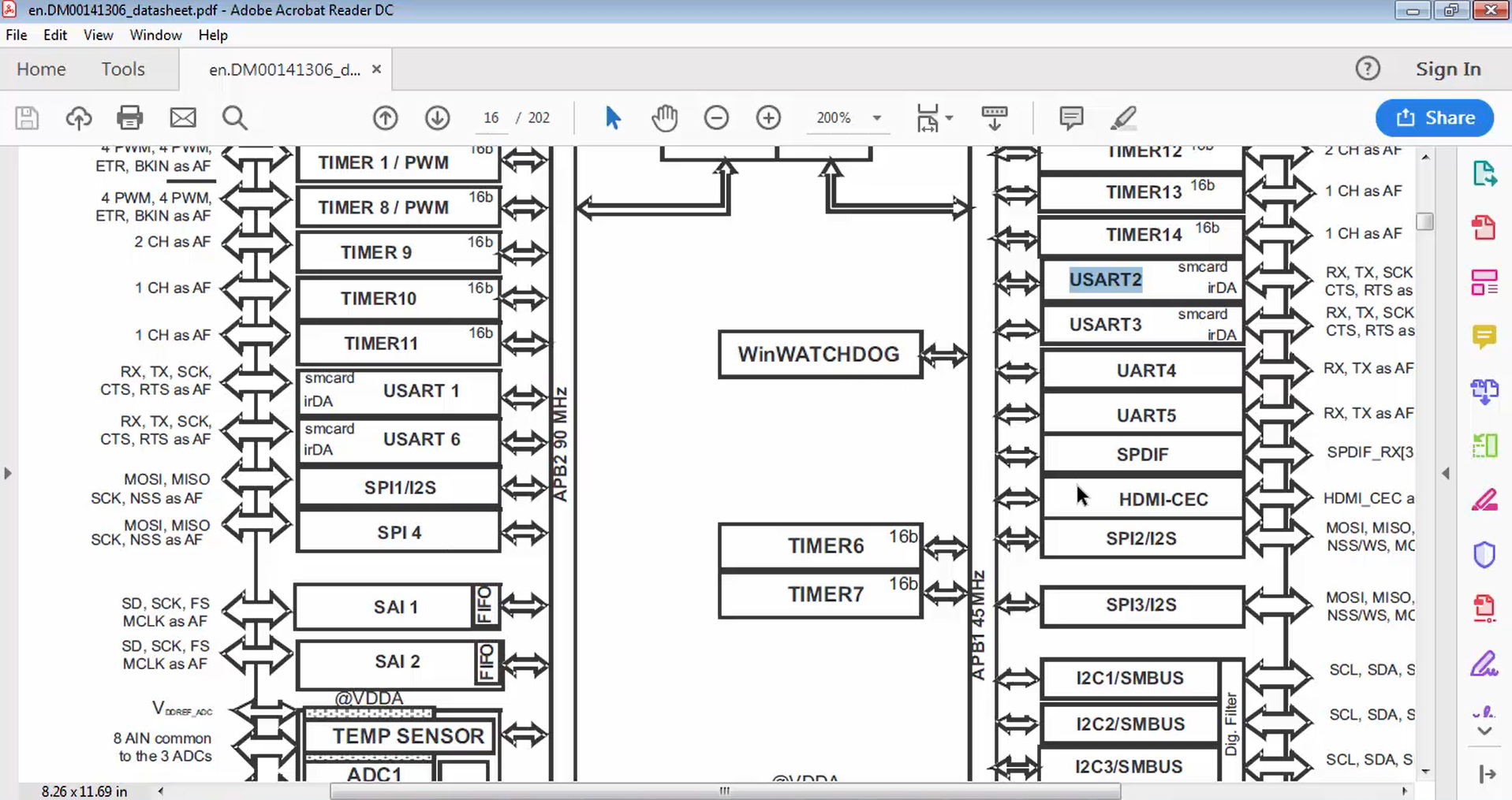
Suppose you open the datasheet of the microcontroller (Figure 1). It has UART1, UART2, UART3 up to 6, i.e., collectively called as USART (Universal Synchronous and Asynchronous Receiver Transmitter) module of the microcontroller, and we use that module in asynchronous mode, we do asynchronous communication. That’s why we call it as UART.
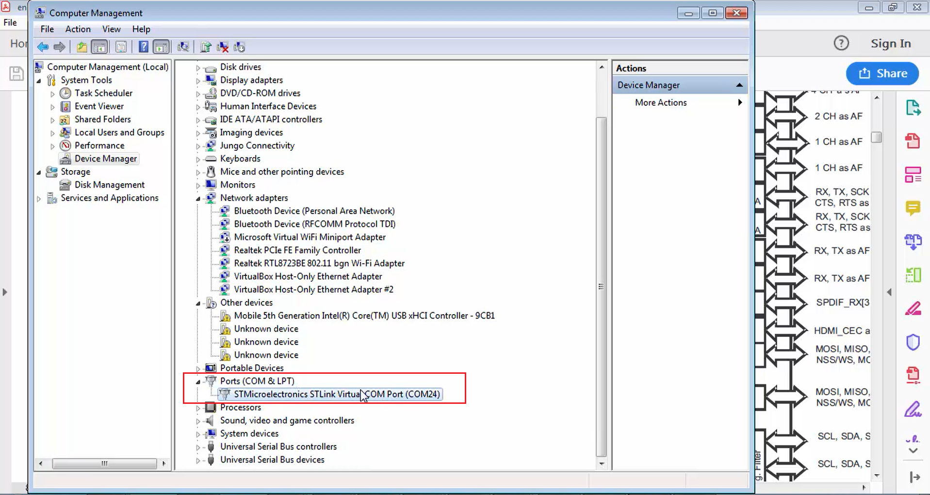
In this project, let’s use UART2. That’s because when you connect a Nucleo board to the PC, in the device manager, in the ports section, the Nucleo board actually enumerates as a virtual COM port (Figure 2).
Our computer communicates with the STM32 Nucleo board over this virtual COM interface. This virtual COM interface is actually enumerated by the firmware present on the ST-link circuitry of the Nucleo board. This virtual COM interface works via the UART2 peripheral of the microcontroller of the Nucleo board.
If you want to know more about that, you have to check the user manual to see which UART peripheral is used to enumerate as a virtual COM port in the computer.
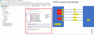
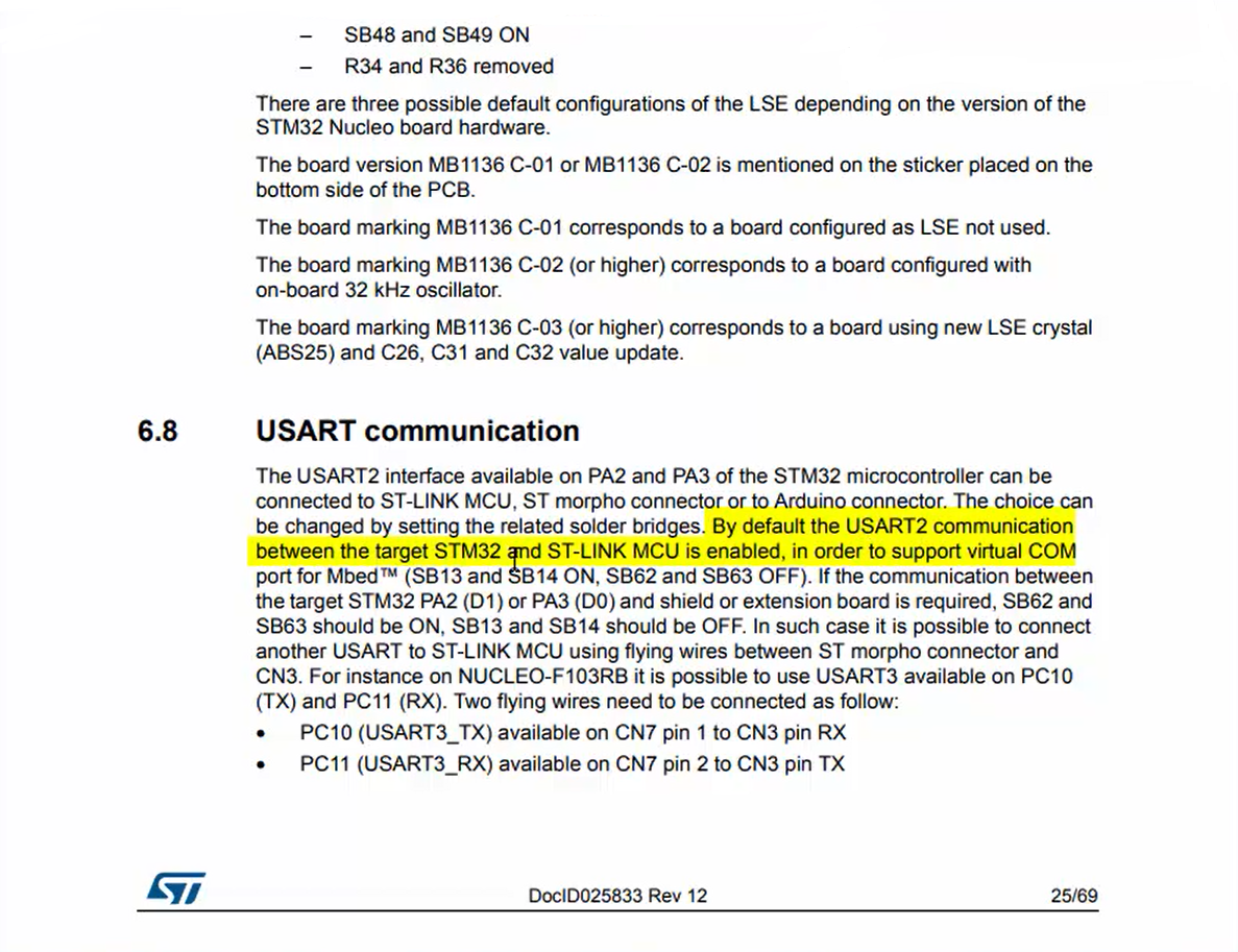
Whatever the board you have, if it supports virtual COM in enumeration, then they will also mention which UART peripheral is used for that purpose. If you go to section 6, i.e., hardware layout and configuration in the user manual, there you will find USART communication. Just click over that. This USART communication section (Figure 3) says that the USART2 peripheral is used for virtual COM purposes.
In Figure 3, you can see that by default, the USART2 communication between the target STM32 and ST-Link MCU is enabled in order to support virtual COM port for embed. This selection of peripheral may not be true in other boards.
For example, in discovery, virtual COM support is not available. So, you have to arrange, or you have to buy one extra USB to UART converter dongle in order to achieve the virtual COM communication between the PC and board if you are using a discovery board. You have to check your board whether the virtual COM support is available on your board or not. From Nucleo, it is available. Even if it is available, by going through the user manual, check which peripheral is used for virtual COM purposes.
If it is discovery, then you probably have to buy USB to UART converter hardware, and then you have to use that. There is a document attached to this lecture that contains information about how to use external USB to UART converter hardware to communicate with the board via PC.
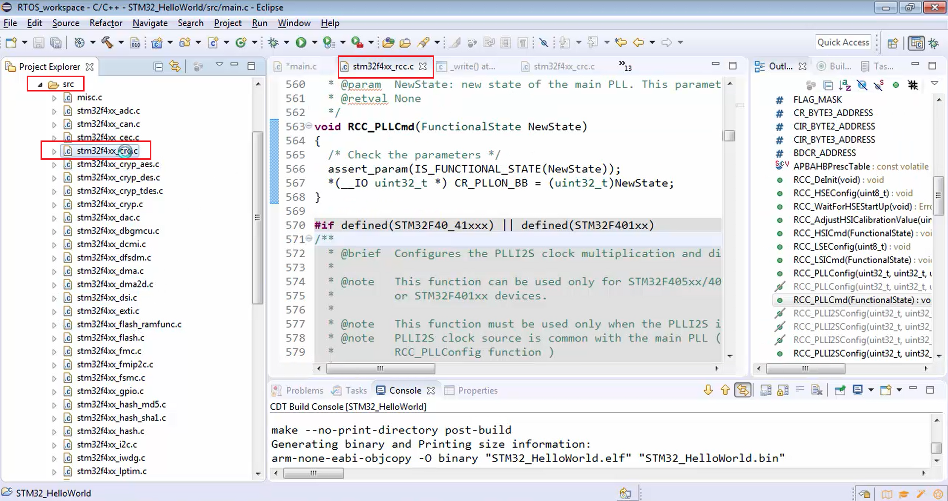
All the clock management codes are written in stm32f4xx_rcc.c.
Now let’s go to the rcc.c (Figure 4). On the right-hand side of Figure 4, you can see various APIs in order to handle the clocks. You can see RCC_AHB1 peripheral clock command (RCC_AHB1PeriphClockCmd), RCC_APB1 peripheral clock command (RCC_APB1PeriphClockCmd), RCC_AHB3 peripheral clock command (RCC_AHB3PeriphClockCmd), etc. Don’t get confused by all these APIs. The concept is very simple.
Just check where exactly the USART2 peripheral is hanging. It is hanging on the APB1 bus (Figure 1). That’s why you have to use the RCC_APB1 peripheral clock command (RCC_APB1PeriphClockCmd). Now let’s use that.
Go to the main.c and type RCC_APB1PeriphClockCmd(), as shown in Figure 5.
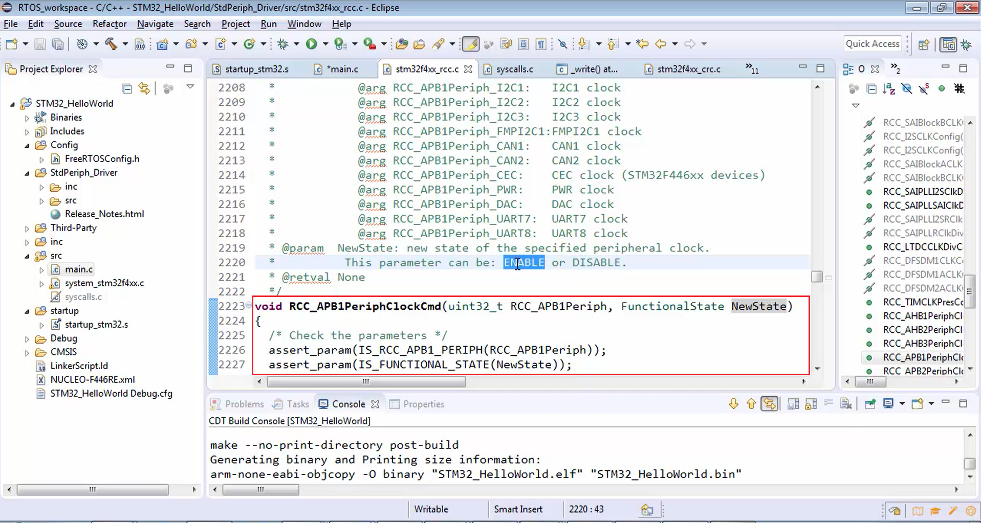
Let’s go and explore this API. This API enables or disables the low-speed APB, i.e., APB1 peripheral clock. RCC_APB1PeriphClockCmd() API takes two arguments (Figure 6).
In the new state, you have to mention whether you want to enable the clock or disable the clock. In this example, we have to use the enable. The first argument is used to describe to whom you want to enable the peripheral clock.
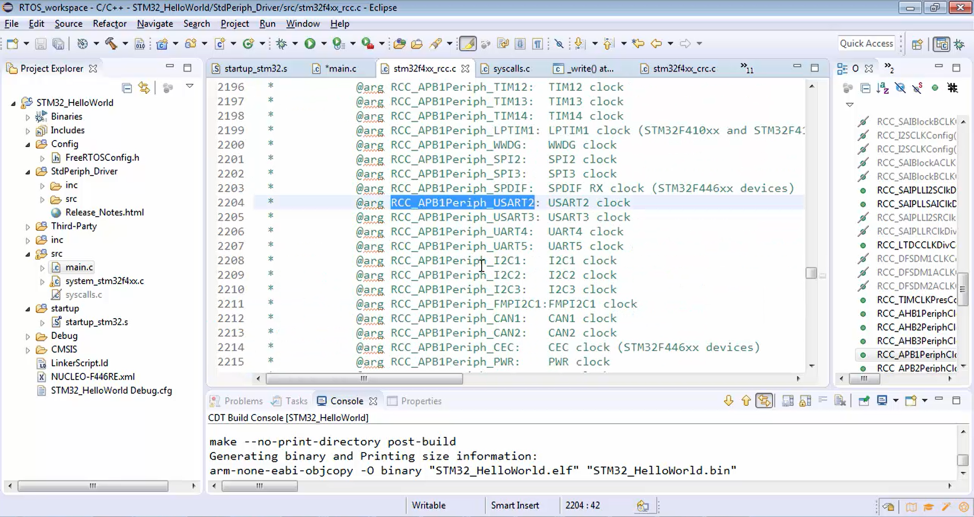
Figure 7 shows the list of all the peripherals hanging on the APB1 bus. To enable the required clock, you have to use USART2 and then enable.

Go back to the main.c and pass the parameters to the function call of RCC_APB1PeriphClockCmd(), as shown below.
static void prvSetupUart(void)
{
   //1. Enable the UART2 Peripheral clock
   RCC_APB1PeriphClockCmd(RCC_APB1Periph_USART2,ENABLE);
}
Call for RCC_APB1PeriphClockCmd() API
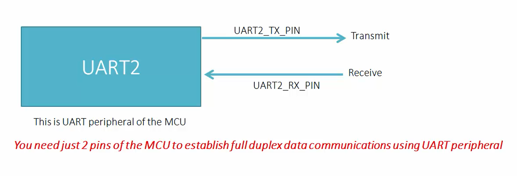
Now the UART communication happens over two pins (Figure 8). One is called UART TX, and another one is called UART RX. Because UART is full-duplex communication where data is transferred over a TX line and the data is received over the RX line.
We have already selected our UART peripheral, i.e., UART2. But you have to find out on what pins of the microcontroller the UART TX and RX happen. Because at the end of the day, the data communication should happen over the microcontroller pins. These details you can get from multiple sources like the pin description table from the datasheet or from the user manual of the board.
If you check the user manual of the board, it clearly says that the UART2 communicates over the PA2 and PA3 pins of the STM32 microcontroller. PA2 means GPIO port A pin number 2, and PA3 means GPIOA pin number 3. You have to find out the TX and RX lines. But the UART2 peripheral of the Nucleo board communicates with PC over PA2 and PA3 pins of the microcontroller. In order to find out the TX and RX lines go and check the datasheet.
Now go to the datasheet. There is something called a pinout and pin description section.
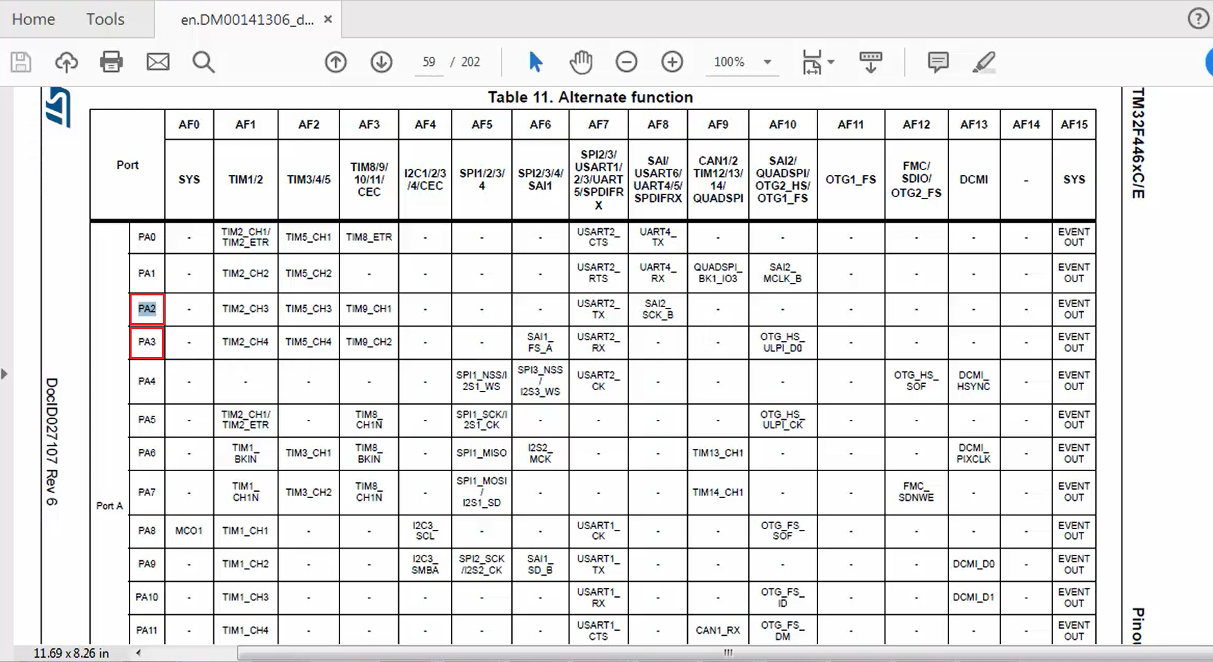
In the pinout and pin description section, go and check the alternate function table (Figure 9). Just search for PA2.
In Figure 10, you can see that PA2 actually acts as USART2 TX when PA2 is kept under alternate function mode 7. There are several alternate function modes available to pins of the microcontroller. PA3 acts as USART2 RX when it is configured in alternate mode 7. This also means that PA2 can act as timer 2’s channel 3 when you configured it in alternate function 1 mode. That means PA2 is TX and PA3 is RX. Let’s note down that information.
2. The second step is to configure the GPIO port A pin number 2 to behave as UART2 TX and GPIO port A pin number 3 to behave as UART2 RX. We call this step a pin alternate function configuration. For this, you have to use the GPIO driver.
Click here to read more.