UART pin configuration using STD. Peripheral Library APIs
- The second step is to configure the GPIO port A pin number 2 to behave as UART2 TX and GPIO port A pin number 3 to behave as UART2 RX. We call this step a pin alternate function configuration. For this, you have to use the GPIO driver of the standard peripheral layer since these are with respect to the pin configuration. In order to configure the pin, you have to refer to the GPIO (General Purpose I/O).
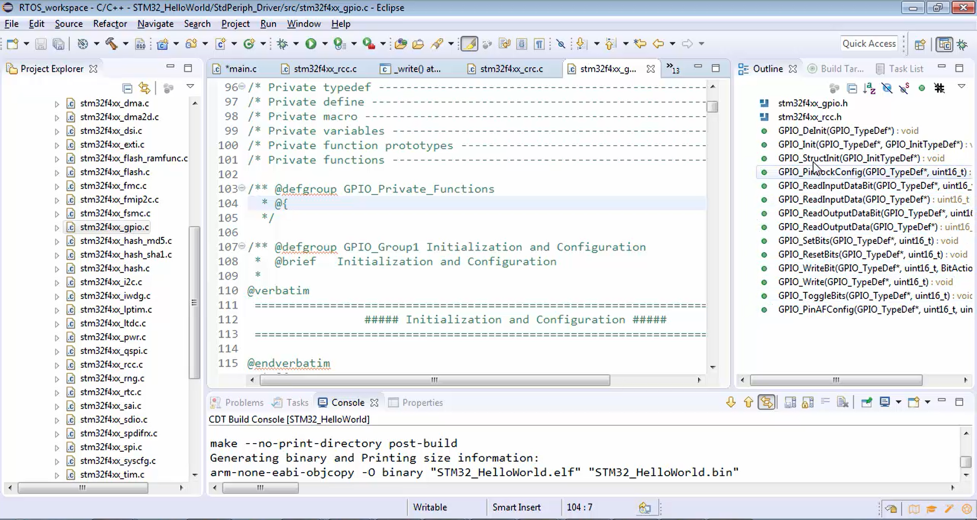
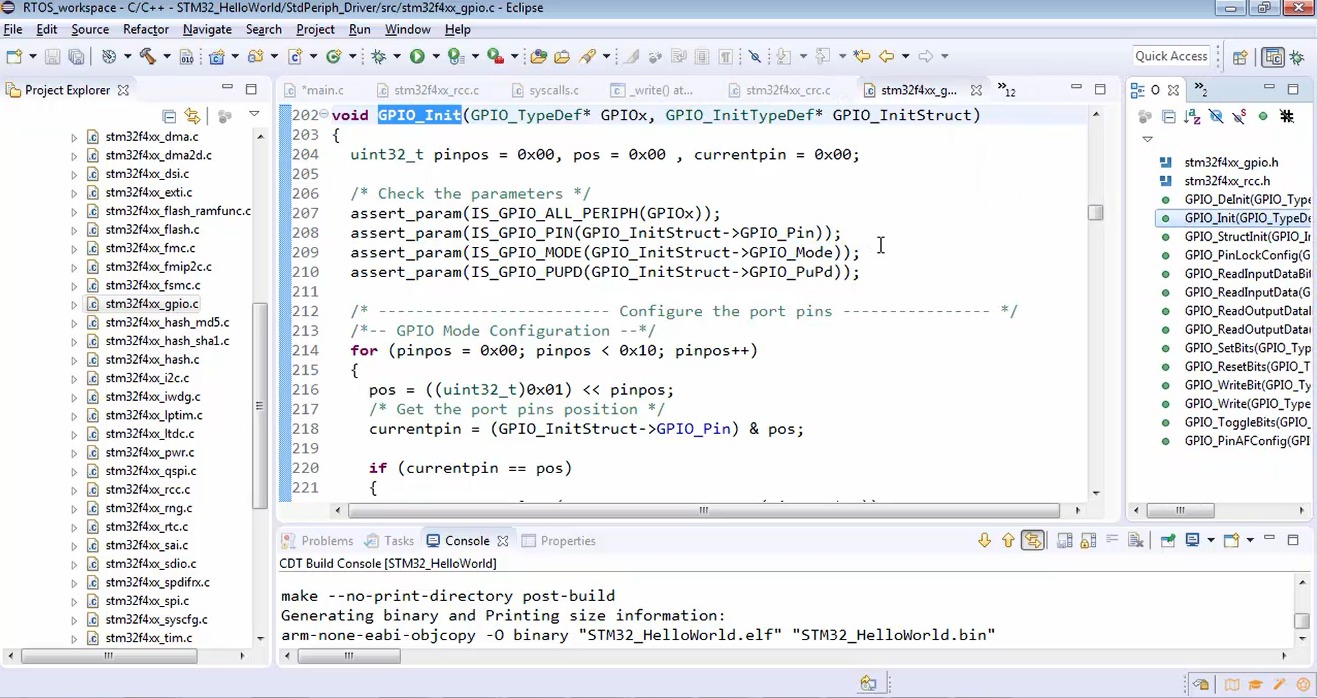
Now let’s go to the GPIO driver (Figure 1), here you will see various APIs in order to handle or change the mode of a microcontroller pin. In GPIO driver, you can see GPIO_DeInit, GPIO_Init, etc.
We are interested in GPIO_Init. Let’s open and explore GPIO_Init (Figure 2).
It initializes the GPIOx peripheral. We are using PA2 and PA3. That means GPIOA pin number 2 and GPIOA pin number 3. So, you have to populate the GPIO_InitTypeDef structure, and then you have to pass the address of that structure as an argument to this GPIO_Init function in order to carry out the initialization.
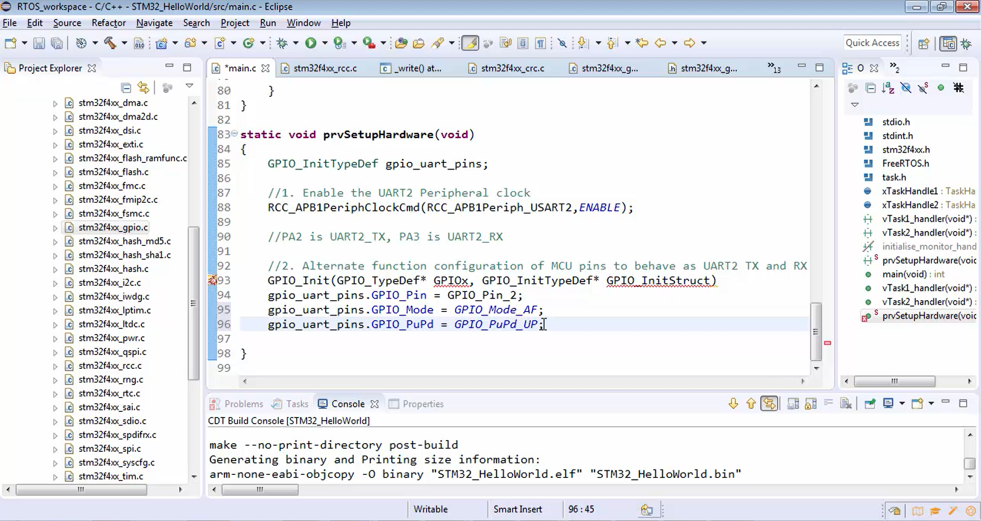
void GPIO_Init(GPIO_TypeDef* GPIOx, GPIO_InitTypeDef* GPIO_InitStruct)
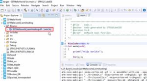
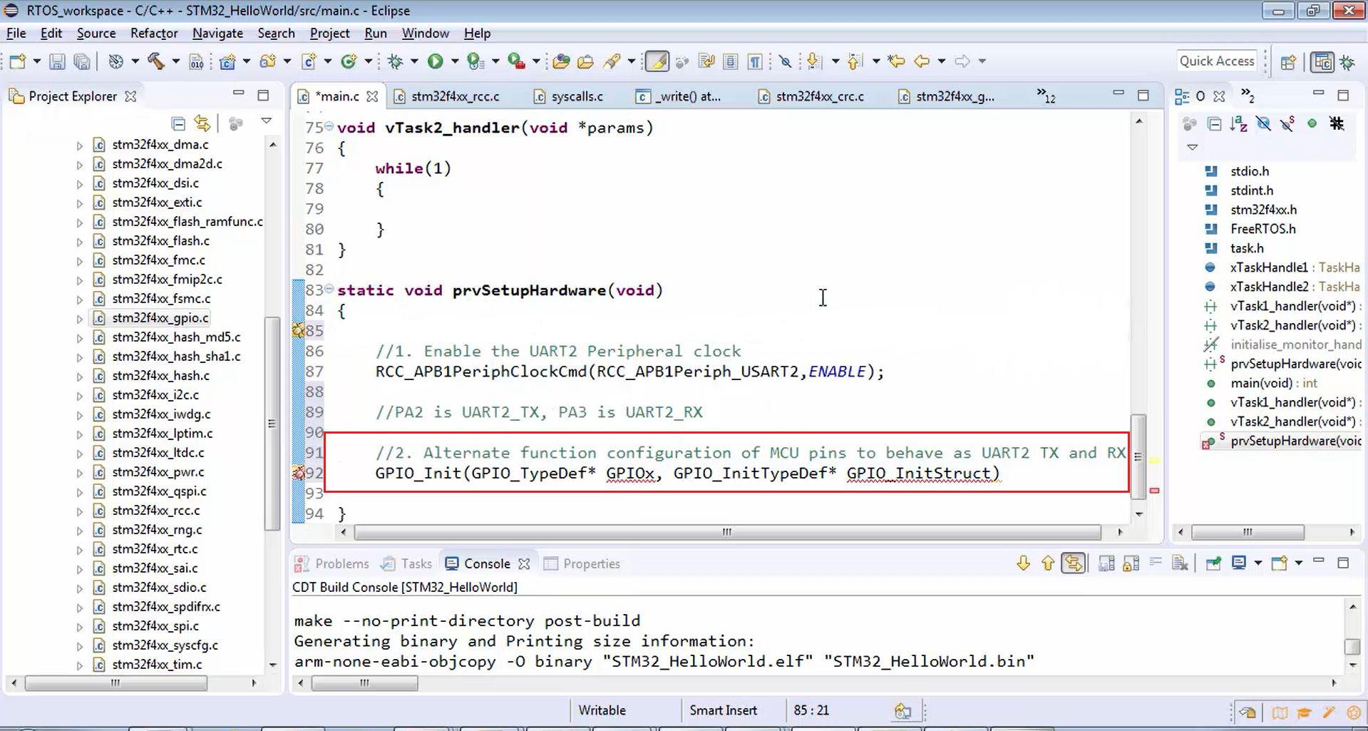
Just copy the GPIO_Init API, go to the main.c, and paste it, as shown in Figure 3.
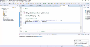
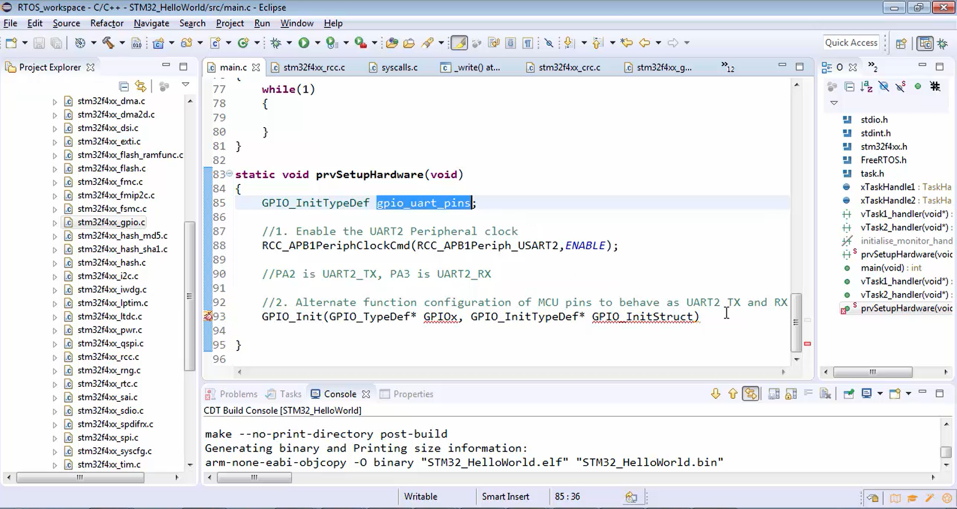
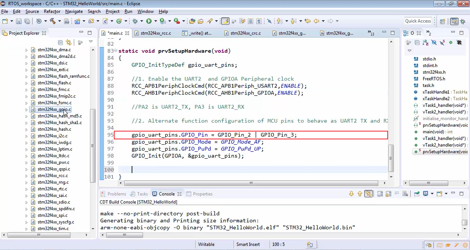
First, let’s create a variable for the structure type GPIO_InitTypeDef and call it as gpio_uart_pins (Figure 4).
Now let’s just populate the structure gpio_uart_pins.
Write gpio_uart_pins, give a dot (.) operator, and let’s start accessing member elements.
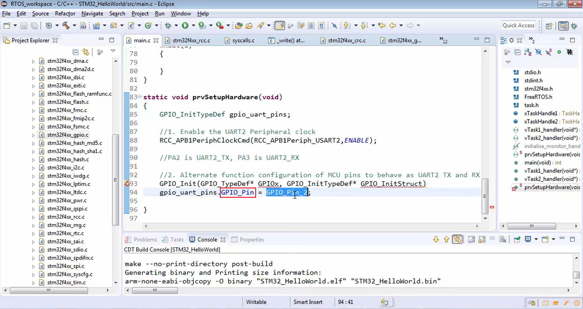
First one, you have to mention what exactly is the pin number. We are using PA2 and PA3. First, let’s configure PA2.
For configuring PA2, you have to use the macros given by the standard peripheral driver. Just type GPIO_PIN_2, as shown in Figure 5.
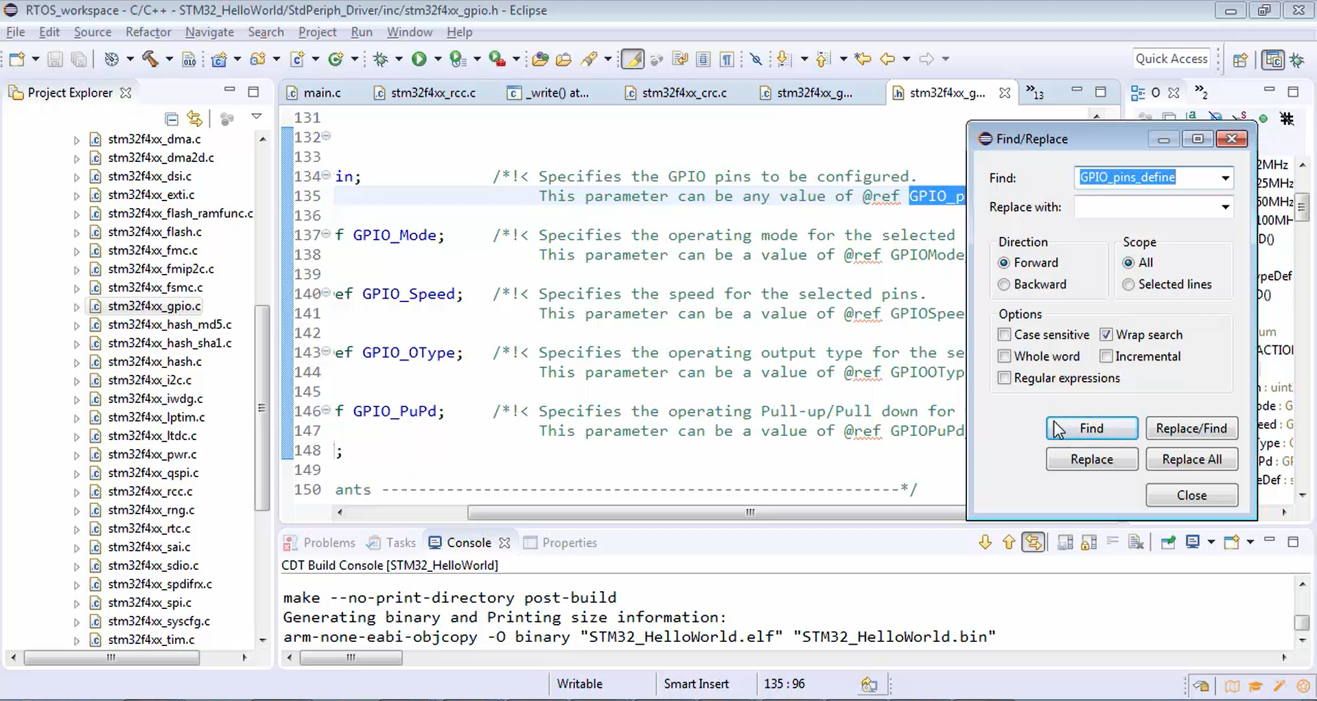
If you don’t understand what exactly is the macro name you have to use, then explore the member element GPIO_Pin marked in Figure 5. There you will find a reference (Figure 6). Always give attention to this ref, and here they are asking you to go and check the GPIO_pins_define.
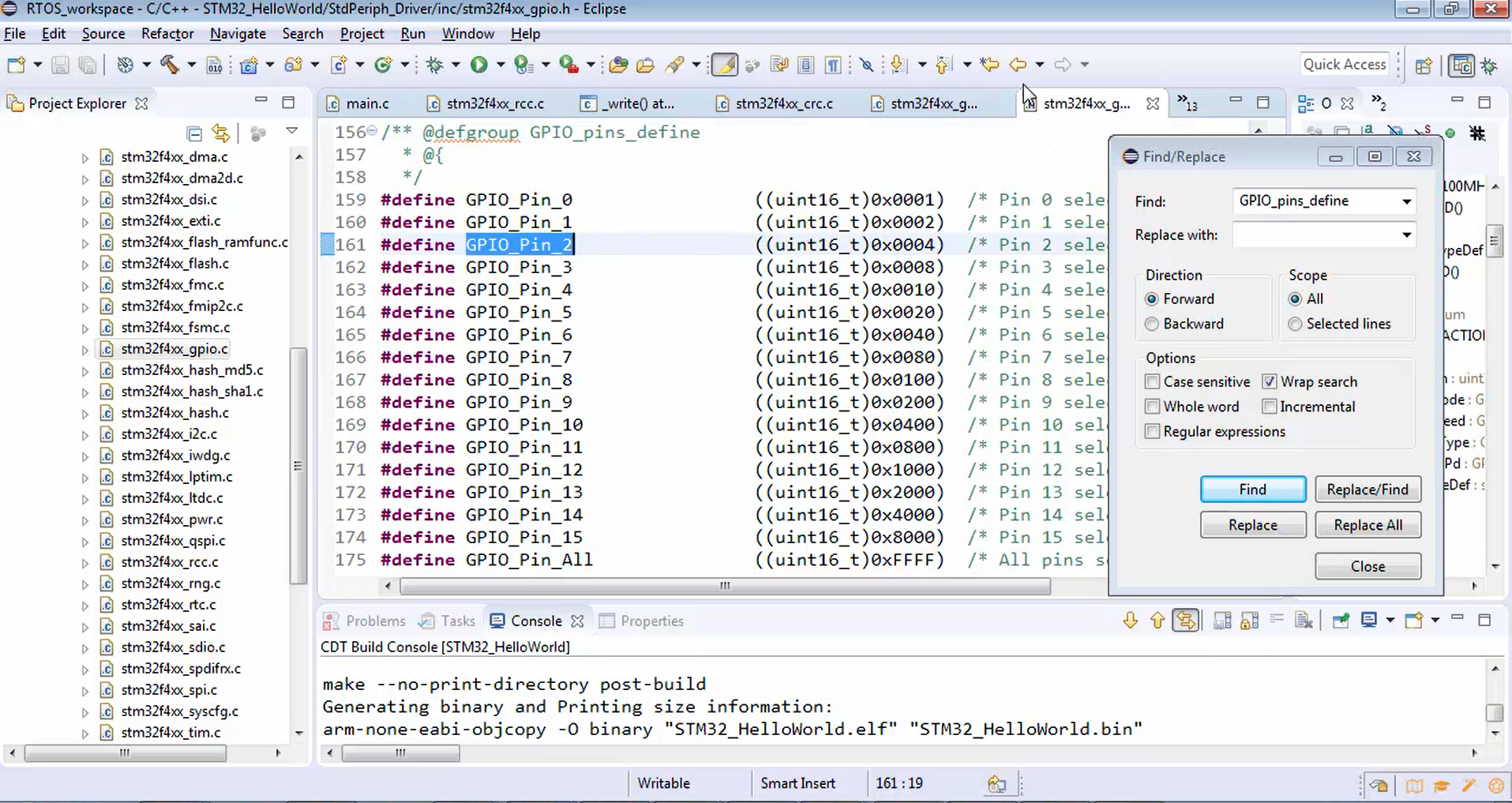
Now copy GPIO_pins_define and search in the header file (stm32f4xx_gpio.h), as shown in Figure 7. It will take you to the pin’s definition (Figure 8); you have to choose one among these. Since we want to configure pin number 2, we used PA2.
typedef struct
{
uint32_t GPIO_Pin; /*!< Specifies the GPIO pins to be configured.
This parameter can be any value of @ref GPIO_pins_define */

GPIOMode_TypeDef GPIO_Mode; /*!< Specifies the operating mode for the selected pins.
This parameter can be a value of @ref GPIOMode_TypeDef */

GPIOSpeed_TypeDef GPIO_Speed; /*!< Specifies the speed for the selected pins.
This parameter can be a value of @ref GPIOSpeed_TypeDef */

GPIOOType_TypeDef GPIO_OType; /*!< Specifies the operating output type for the selected pins.
This parameter can be a value of @ref GPIOOType_TypeDef */

GPIOPuPd_TypeDef GPIO_PuPd; /*!< Specifies the operating Pull-up/Pull down for the selected pins.
This parameter can be a value of @ref GPIOPuPd_TypeDef */
}GPIO_InitTypeDef;
Reference for GPIO_Pin

No need to configure the GPIO_Speed that is not relevant. So, let’s use the default value there in the microcontroller. We took the default speed because this speed does nothing with the UART baud rate. This is pin transition speed, i.e., the switching speed of the GPIO engine so, we need not configure it.
After that, let’s configure the mode.
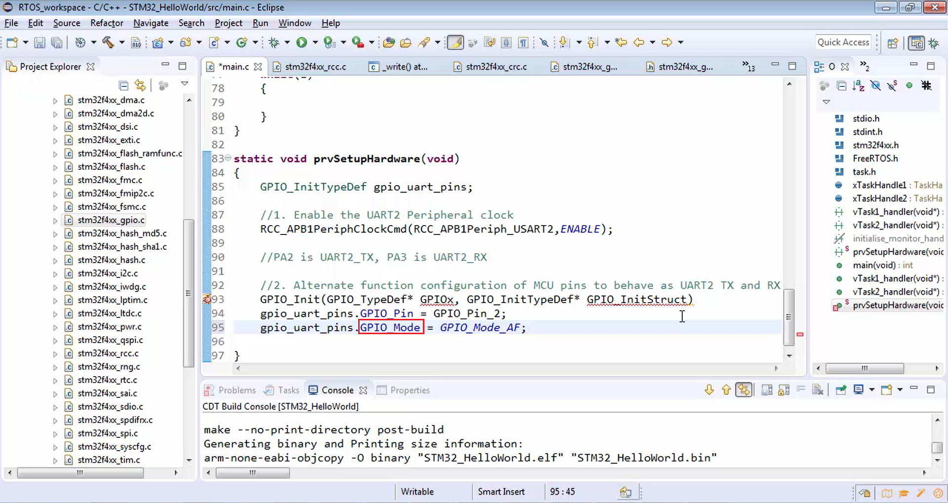
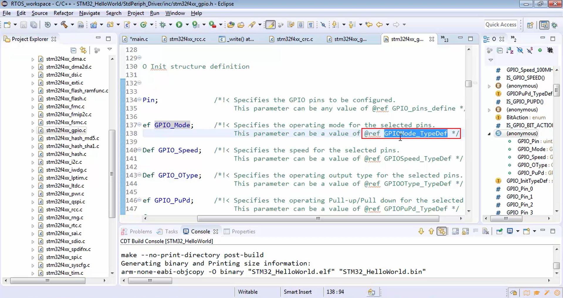
Now we don’t know what exactly the mode we have to use. To know the mode information, just go to the GPIO_Mode marked in Figure 9 and explore from the reference shown in Figure 10. This specifies the operating mode for the selected pins.
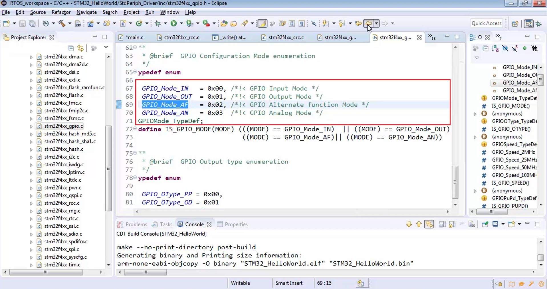
Now let’s see what are the modes available.
For that, just copy the GPIOMode_TypeDef (Figure 10) and search in the header file (stm32f4xx_gpio.h), as shown in Figure 11.
Now in Figure 12, you can see all the available modes. You can put the I/O as GPIO_In, GPIO_Out, alternate function, or analog mode.
In this example, we are giving the GPIO pin to the UART peripheral. UART is going to use that pin. That’s why the mode is actually an alternate function mode. We are using the pins for alternate functionality, i.e., UART functionality. To be specific we are using PA2 as UART TX. That means we have to assign alternate functionality to that pin. That’s why, for PA2, we have to select mode as GPIO_Mode_AF (Figure 9).

Now let’s proceed to configure the output type. The output type is actually not usable for this configuration because the mode is not output mode. That’s why there is no need to configure the output type. Leave it as it is.
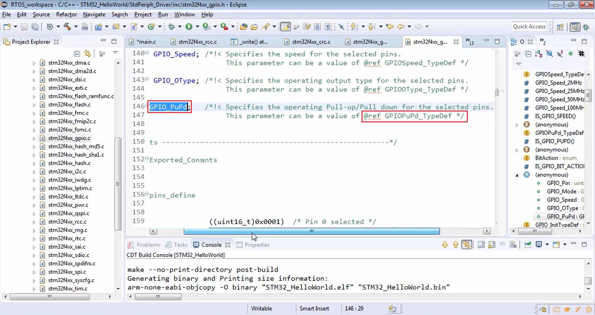
Next, we have to configure pull up or pull down.
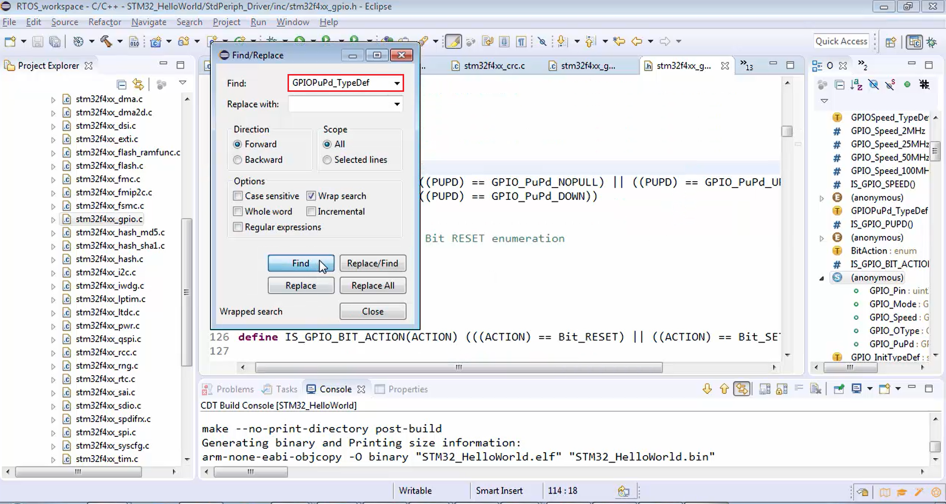
Now let’s see what are the options available for pull up or pull down. Go to the GPIO_PuPd member element shown in Figure 13. Copy the reference GPIOPuPd_Typedef and search for it in stm32f4xx_gpio.h, as shown in Figure 14.
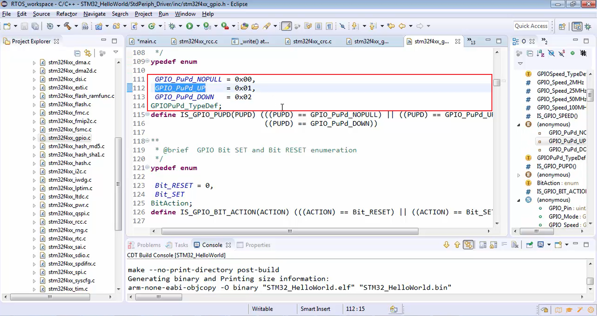
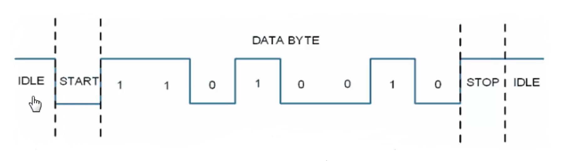
Look at Figure 15. You have a couple of options for pull up or pull down. For this example, let’s go for GPIO pull up/ pull down as pull up (GPIO_PuPd_UP) because whenever the UART TX or RX line is idle, the bus state will be high, i.e., logical 1.
If you observe the UART communication shown in Figure 16, when the line is idle, then it is pulled to high. Idle means no message is getting transferred over the TX and RX line. That’s why we made GPIO_PuPd as UP (Figure 17).
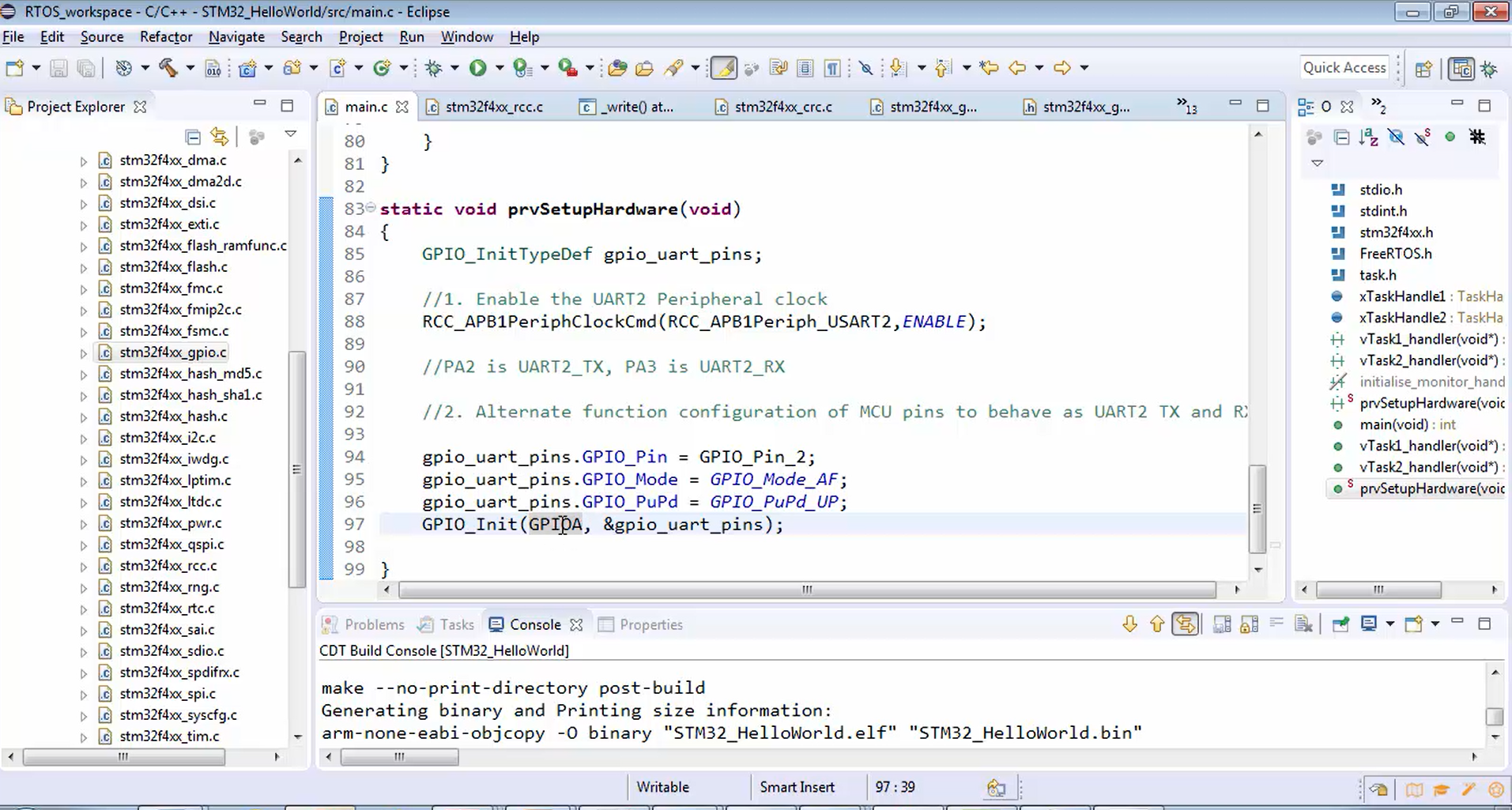
After all the above configuration, call GPIO_Init function (Figure 18) and let’s send the address of the structure variable, i.e., gpio_uart_pins as the second argument of it. The first parameter is the base address of the GPIOA peripheral.
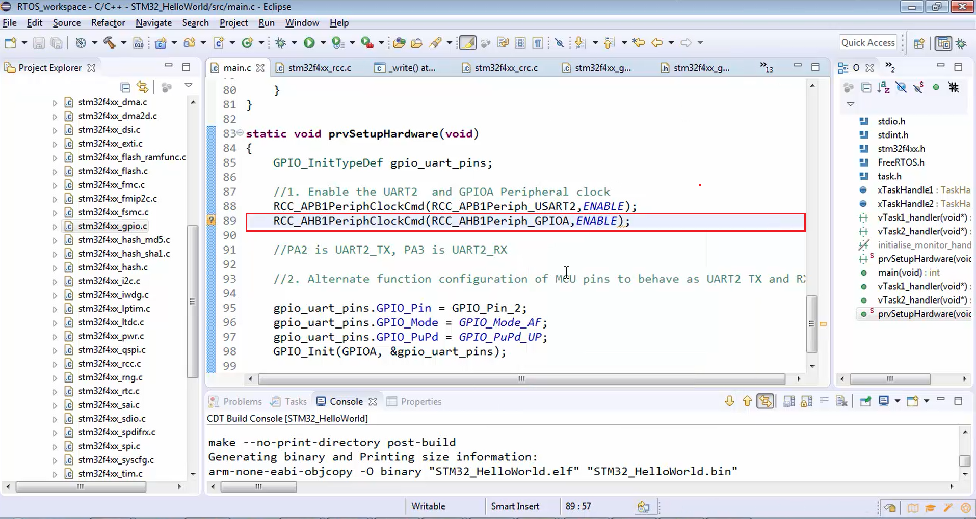
In Figure 18, we are actually doing configuration to GPIOA peripheral to behave as the alternate function mode. That’s why we have to enable the GPIOA peripheral clock, which we can do, as shown in Figure 19. Since the GPIOA peripheral is hanging on the AHB1 bus, you have to enable the AHB1 clock.
Here you have to configure both pin 2 and pin 3. That’s why let’s do bitwise OR of GPIO pin 2 and GPIO pin 3 (Figure 20).
Now both the GPIOA pin numbers 2 and 3 are configured for alternate functionality mode by doing some settings into the GPIOA registers. Since we touch the GPIOA registers, we have to enable the clock for that. Because before configuring the GPIOA, it should be alive.
Now let’s go to the GPIO driver once again.
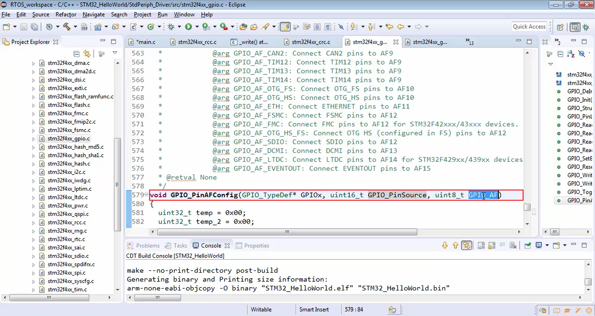
There is one more API called GPIO_PinAFConfig, i.e., GPIO pin alternate function configure. For this function, you have to mention the pin source and its alternate functionality mode (Figure 21). It is very easy to understand if you check the datasheet.
Let’s go to the datasheet once again and go to the alternate function (Figure 22).
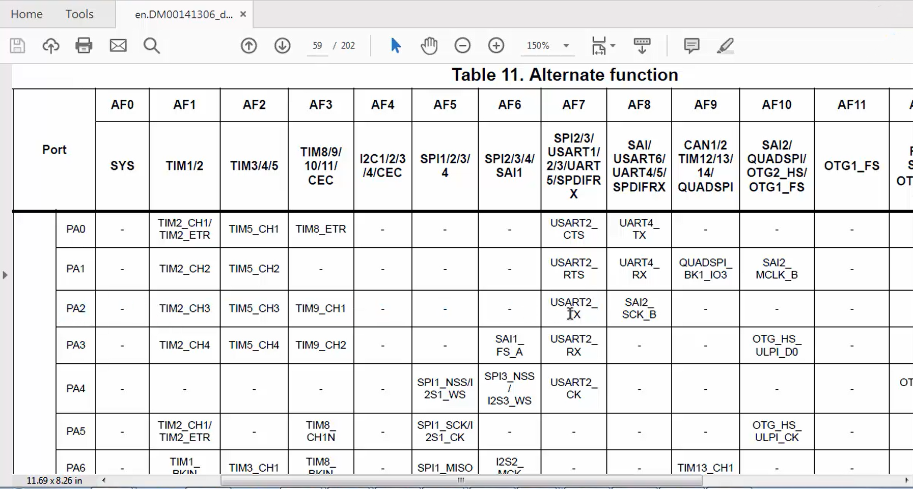
According to the table given in Figure 22, the PA2 can act as TX only when the alternate function mode is 7, and also remember that PA2 cannot act as RX. That means you can never be able to achieve PA3 acting as TX. The microcontroller will not allow PA3 to act as TX. So, PA2 can act as TX when it is configured for AF7, and PA3 can act as RX only when you configure it in alternate function 7.
Now let’s do that using the GPIO_PinAFConfig function. You have to mention the pin source as a second parameter. The pin source specifies the pin, and the third parameter is alternate functionality mode.
- The third step is AF mode settings for the pins (Figure 23). For GPIO_PinAFConfig, first, you have to mention the peripheral base address, i.e., GPIOA.
The next parameter is pin source, i.e., PA2, and you have to keep in alternate function mode AF7, i.e., GPIO_AF_USART2. If you check the macro GPIO_AF_USART2, then that is nothing but 0x07, as expected. Now, PA2 is configured as TX.
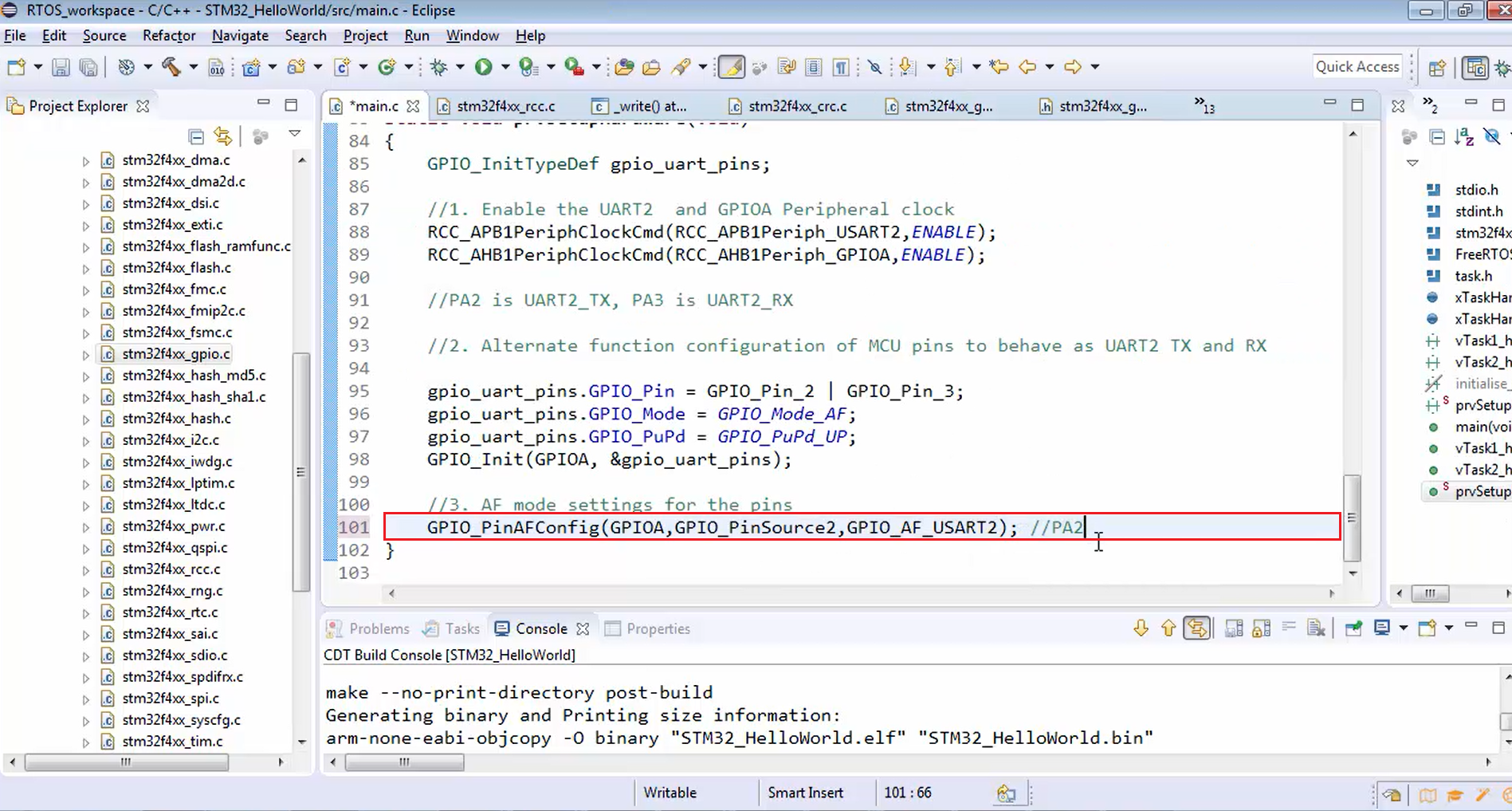
Now let’s do the same thing for PA3. Just change the pin source to GPIO_PinSource3 here. Now, PA3 will be behaving as UART2 RX.
static void prvSetupUart(void)
{
   GPIO_InitTypeDef gpio_uart_pins;

   //1. Enable the UART2 and GPIOA Peripheral clock
   RCC_APB1PeriphClockCmd(RCC_APB1Periph_USART2,ENABLE);
   RCC_AHB1PeriphClockCmd(RCC_AHB1Periph_GPIOA,ENABLE);

   //PA2 is UART2_TX, PA3 is UART2_RX

   //2. Alternate function configuration of MCU pins to behave as UART2 TX and RX

   gpio_uart_pins.GPIO_Pin = GPIO_Pin_2 | GPIO_Pin_3;
   gpio_uart_pins.GPIO_Mode = GPIO_Mode_AF;
   gpio_uart_pins.GPIO_PuPd = GPIO_PuPd_UP;
   GPIO_Init(GPIOA, &gpio_uart_pins);

   //3. AF mode settings for the pins
   GPIO_PinAFConfig(GPIOA,GPIO_PinSource2,GPIO_AF_USART2); //PA2
   GPIO_PinAFConfig(GPIOA,GPIO_PinSource3,GPIO_AF_USART2); //PA3
}
Configuring PA3 as UART2 RX
- The fourth step is UART parameter initializations.